ER14 – Assembly Guide
- Intech ER14 - Bill De Long - Build -
Build Notes:
Diff fluids (3-5-1) and black grease included
Need to supply shock oil and blue thread lock
Box wrench included for adjusting camber links, need to provide 1.5mm, 2.0mm and 2.5mm hex wrenches
Threads on ball studs in the shock tower need thread lock, the threads are barely long enough to feed into the metal lock nut but not long enough to bite into the nylon locking material
3mm reamer
and light sanding may be necessary on caster blocks
Recommended Upgrades:
Nothing! This car is built like a tank, they've included every possible aluminum upgrade that someone would need in the original kit, as far as 1/10 4WD buggies go, this is one of the toughest on the market!
Current Electronics:
Radio:
BER-TRC1
Servo:
Turnigy 1251
ESC:
SkyRC Toro 120A
Motor:
Turnigy Track Star 8.5T
Battery:
Turnigy Ultimate Shorty 2S-90C-4.6A
Setups:
Available Spur Gears: 81T, 84T, 87T
IDR: 35T Crown / 14T Pinion = 2.5 IDR
3 different motor layout options available
Hits:
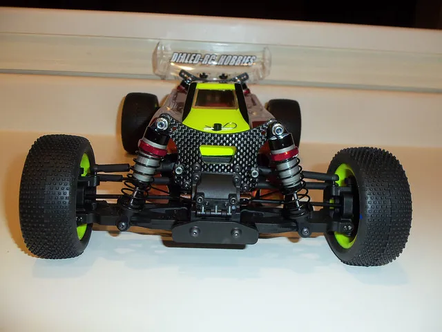
4mm Carbon Fiber Shock Towers
Aluminum: hexes, suspension pin block (all 4)
Lightened outdrives
Spring captured CVD pins (no set screws to fuss with)
Very little slop, all linkages are butter smooth
Super easy build with excellent instruction and parts organization, right on par with Tamiya qualityIncludes clear body and wheels (compatible with Kyosho)
Misses:
DialedHobbies is currently the only distributor in the US, it would be nice to see a wider range of parts availability from multiple resellersNeed to add 13mm of spacers + 3x20mm screw to body mountsNo transponder mount, but very easy to tap holes on upper deck
Box Opening:
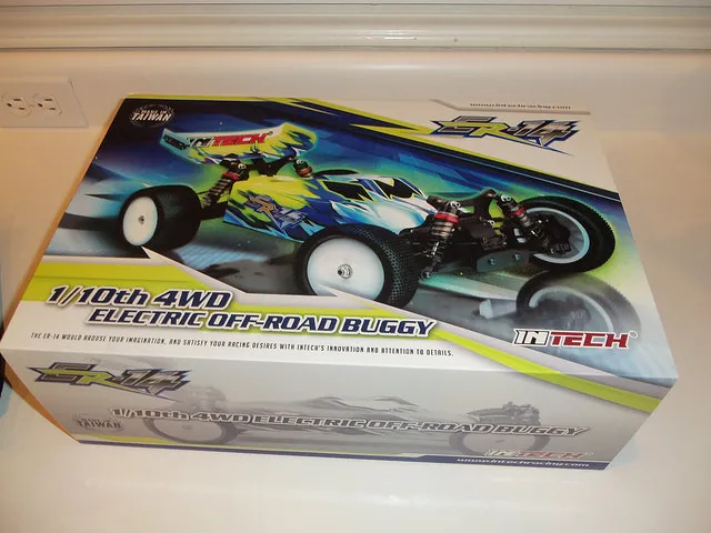
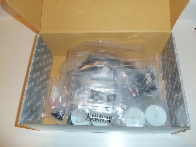
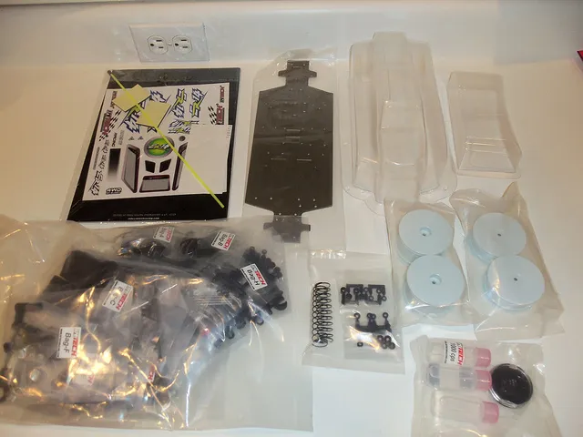
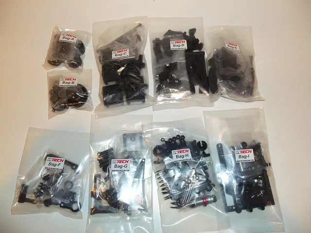
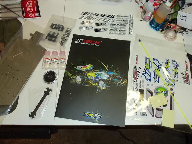
I finally have some free time and I'm going to get started with the build. Very happy to see that it comes with grease, diff fluids and box wrench (No shock oil). There are also addendum spacers and springs included. The manual is printed in nice thick auto dealer brochure quality stock and they've updated portions of the manual with printed decals with corrections. I really like that they've done that as opposed to some manufacturers that slide in a piece of paper addendum which makes it more difficult to keep track of the changes during the build. So far I'm very impressed with everything that I see:
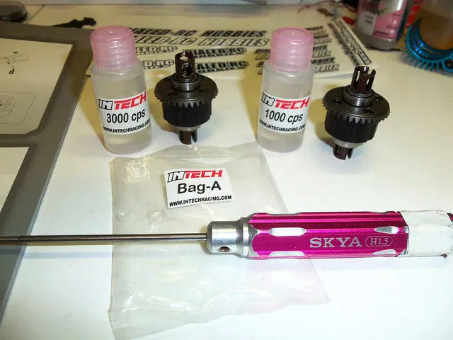
BAG A: Front + Rear Diffs
There are no numbered steps in the manual, they are ordered alphabetically by bag label and all needed parts are contained in each bag making it very easy and quick for assembly.
I couldn't help but notice that the outdrives are lightened 7075 aluminum and they even cut the shafts on a lathe to minimize the amount of friction inside the plastic housing to keep the diff buttery smooth.
The instructions wanted both the front and rear diffs to be filled with 3K fluid but the kit actually came with 1K too, so I'm going to fill the rear diff with 1K to start with. Although the kit supplied black grease, I've decided to use green grease as I already have a grease gun with a rubber nose tip to make it a simple application with minimal mess.
My only concern so far is that they are using 1.5mm screws to secure the bevel gears... I would've preferred 2mm screws, but I suppose the given size of the diffs it's appropriate. I just hope the screws hold up over time as I perform maintenance and they don't strip out on me.
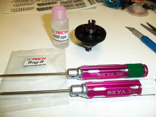
Bag B: Center Diff
Went together the same as the front/rear diffs, I like that the 81T spur gear is replaceable (using 2mm screws), plus there are optional 84T and 87T spurs available. I filled it with included 5K fluid:
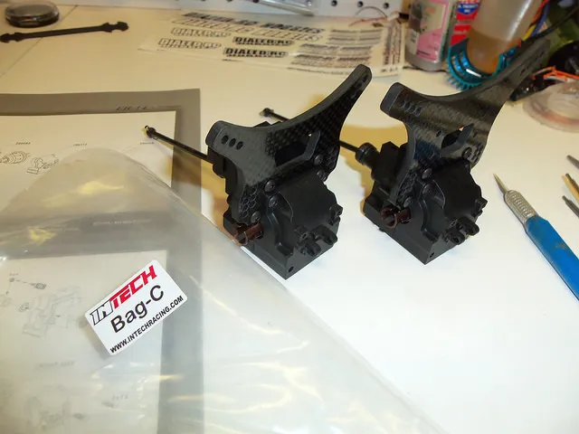
Bag C: Front + Rear Gear Box Assembly
Everything goes together just like a mini 1/8 scale design, very straight forward. I really like the CVD's on the center shafts, plus they use spring clamps to secure the pins instead of set screws, this makes for an extremely efficient design without risk of throwing a pin. They include 4mm carbon fiber shock towers. The more I work on the build the more I am impressed with this kit!
Bag D: Rear Suspension Arm Assembly
Ah yes, the "D-Bag", doesn't matter what kit anyone puts together, this is always everyone's favorite step ;)
I know I mentioned this earlier, but I want to share a close up of how the springs are snapped over the CVD pins making this my favorite CVD assembly I've ever had the pleasure to own:
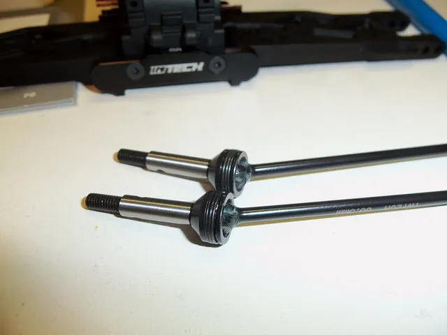
Both the front and rear toe plates are made of aluminum along with aluminum hexes. They even include steel pivot balls for the suspension arms which is typically an upgrade for most brands of cars. The ball studs use a 2.5mm wrench which is really nice, making it very unlikely to strip out. There was no slop anywhere in the linkages and no reaming was necessary for any of the pins. This car is going together without a single problem so far and is by far the best quality build I've ever had the pleasure to assemble, probably better than a Tamiya kit!
I had to be careful not to over tighten the rear toe block so it wouldn't bind with the suspension arm, I backed each screw about a 1/4 turn so each arm would drop effortlessly when the binding was freed up.
The threads on the ball studs were just long enough to go through the shock tower and bite into the lock nuts, however they didn't feed deep enough into the nylon portion of the lock nuts so I used thread lock to secure the nuts on the shock tower. I have to wonder if they originally used 3mm thick shock towers and may have recently upgraded to 4mm thick plates but over looked the extra 1mm of thread needed to feed into the lock nut? It's really no big deal to apply some thread lock, it's still secured perfectly fine.
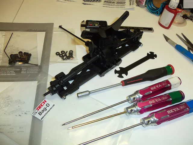
*** Note that I decided not to install the rear sway bars at this time, I'm going to try to get max rear traction and if I run into problems with the car pushing on power, then I'll consider adding the rear sway bars later.
Bag E: Front Suspension Arm Assembly
The caster blocks were still attached to the injection molds and they needed to be bored out with a
3mm reamer
as well as sanded on the front opening to prevent excess binding:
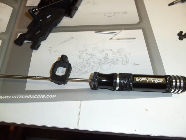
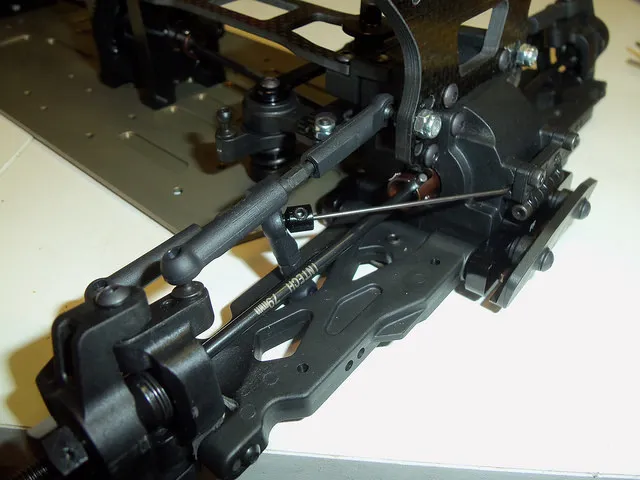
They did a really good job with the design of the sway bar assembly which is identical in layout to most high end buggies with no slop, the rest of the links feel butter smooth and sturdy:
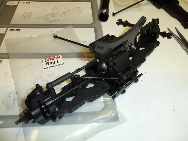
*** I ended up going back and re-doing this step, if you look in the pic above you might notice that I swapped out the inside ball cups because I went with the shortest link possible on the front. I later realized that the ball cups would support going all the way into the notch on the turnbuckle, here is my correction using original parts:
Bag F: Steering Rack
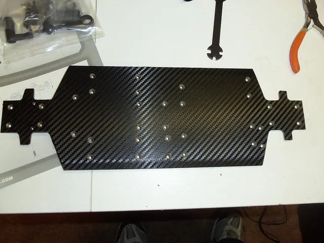
I decided to apply some vinyl covering to help protect the bottom of the chassis from light scratches:
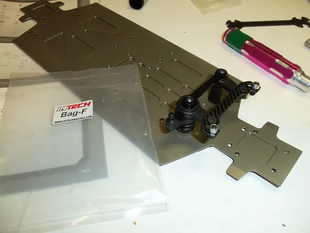
The steering rack uses a carbon fiber ackerman plate and includes a spring loaded servo saver backed with bearings and aluminum top plate.
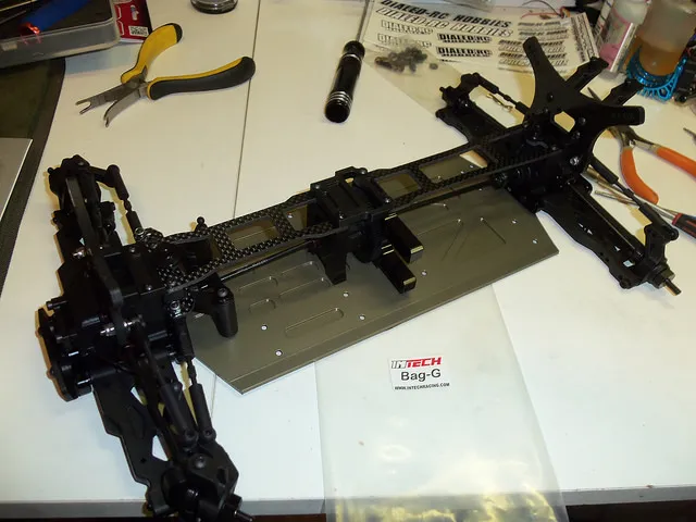
Bag G: Install Diffs
The center diff brackets are all aluminum and they include a slide lock so you don't have to remove any screws from the bottom of the chassis when servicing the center diff, nor do you have to remove the motor:
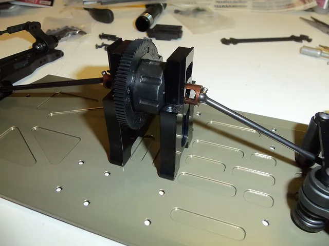
The car is really starting to take shape:
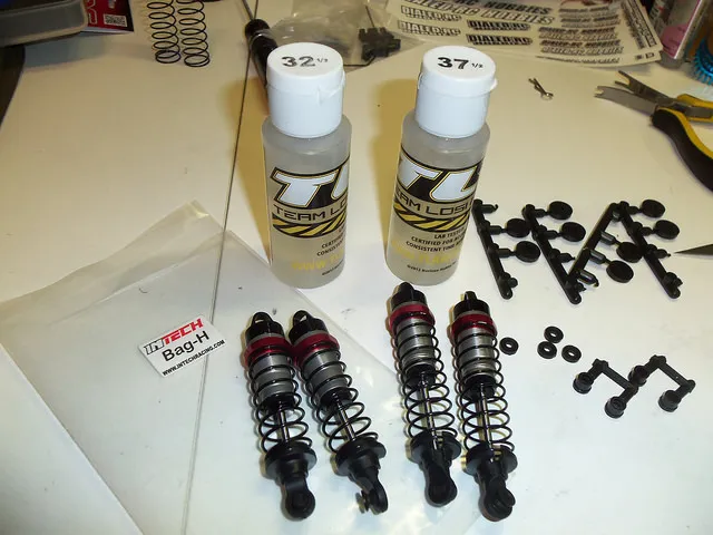
Bag H: Shocks
The shocks are solid aluminum threaded and very nice quality. I measured the pistons and will consider installing some MIP 2 stage pistons later.
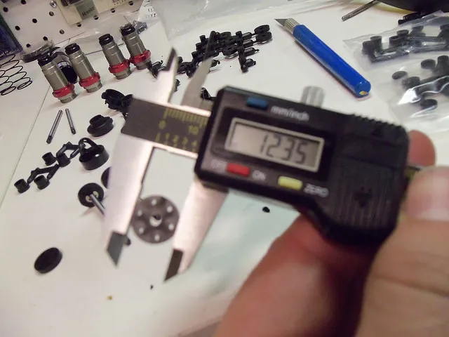
I used 1.1mm pistons on the front and 1.3mm pistons on the rear
I filled the front with 37.5W oil and the rear with 32.5W oil
0% rebound all the way around, I might add 50% rebound on the rear if it starts to bottom out from big jumps.
Bag I: Final Assembly
This step is going to take the longest... the easy part is over, I'd estimate the total build up to this point to take roughly 4 hours. Now I need to install the electronics and trim/paint the body + glue the tires.
Here's a quick peek of bottom of the chassis:
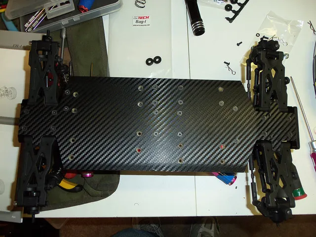
There are no fasteners to secure the servo wiring so I'm using "Amazing Goop" glue to route the servo wire on the chassis and under the front center drive shaft. I'm using duct tape to hold the wire in place and then will peel away the tape after the glue sets up:
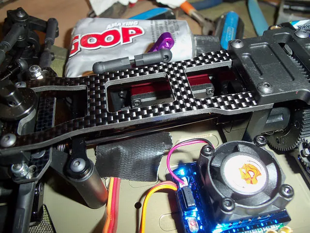
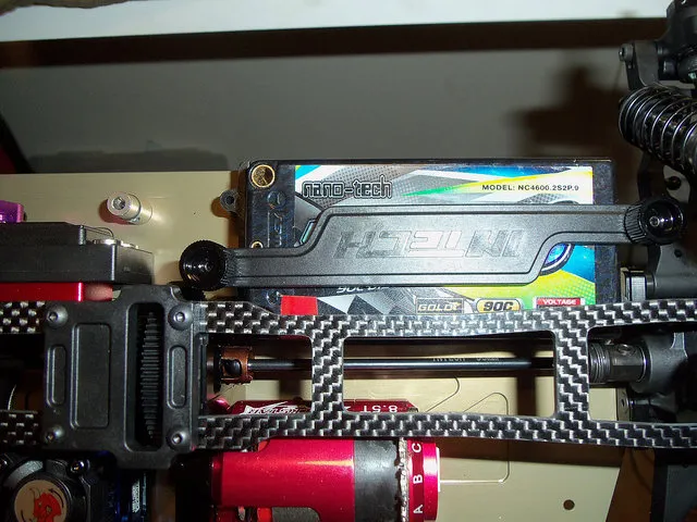
I just discovered my first build issue... the rear upper deck is blocking one of the battery posts, this requires the battery to be removed in order to disconnect the plug. I'm going to have to come up with an alternate solution because I prefer to leave my battery installed in each car when I charge my LiPo's between rounds of racing at the track:
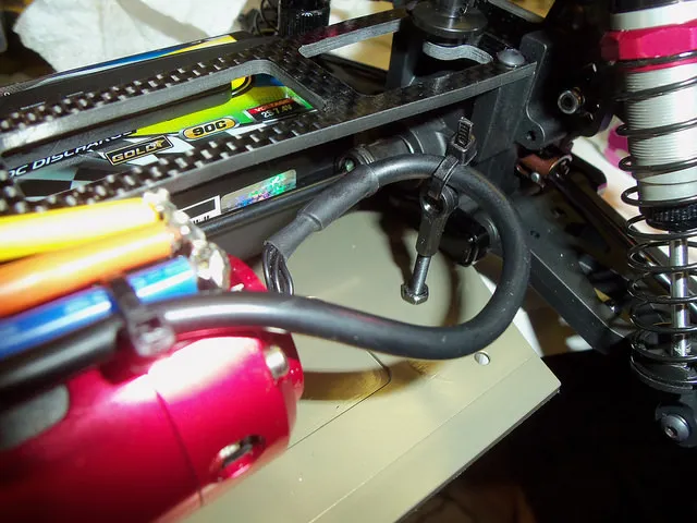
The sensor cable that came with my motor had some extra slack and there's very little room for extra wiring so I mounted a hook using a 3x20mm screw locked with a nut and placed a ball cup on the end to fasten the wire so it doesn't get tangled up on anything:
Here's a full view of the layout with all the electronics installed:
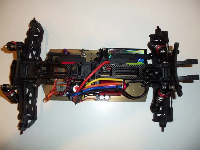
I tapped some 3mm holes on the upper deck to mount my transponder:
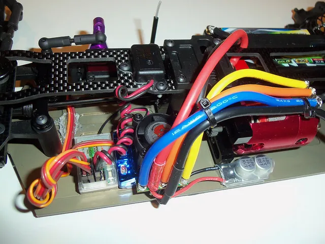
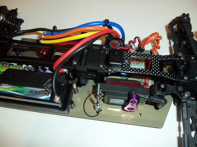
The antenna is fed under the front shaft as well and installed next to the servo. I decided to use countersink washers to mount the servo instead of the included screws to give better protection on the mounting tabs of the servo. I also used an aftermarket aluminum servo horn instead of the stock plastic horns that came with the kit. They include 23T, 24T and 25T splines.
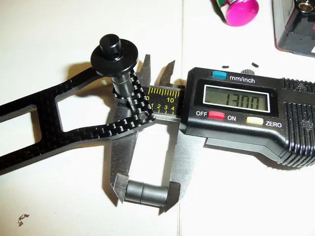
When trimming and test fitting the body, I learned that they goofed on the height of the body mount. I needed to use 3x20mm screws and 13mm worth of extra spacers to raise the height of the mounts so the body would fit properly:
After raising the body mounts 13mm, I now get a decent fit:
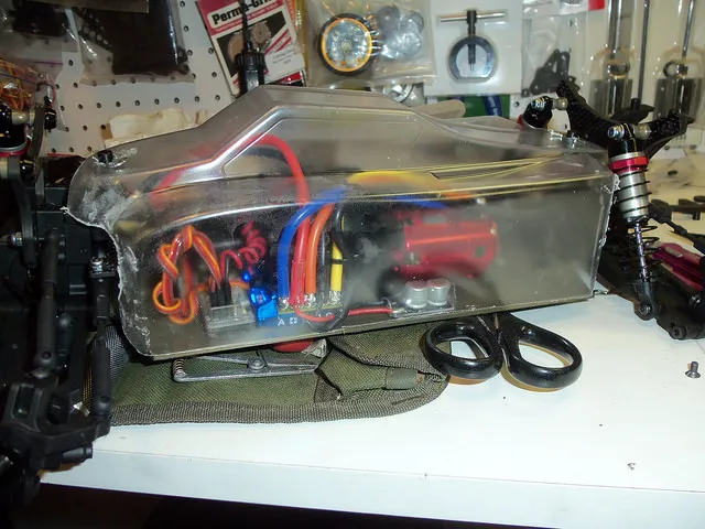
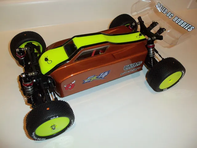
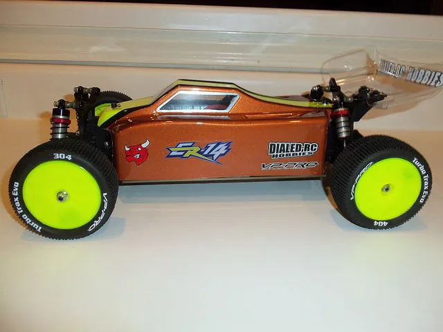
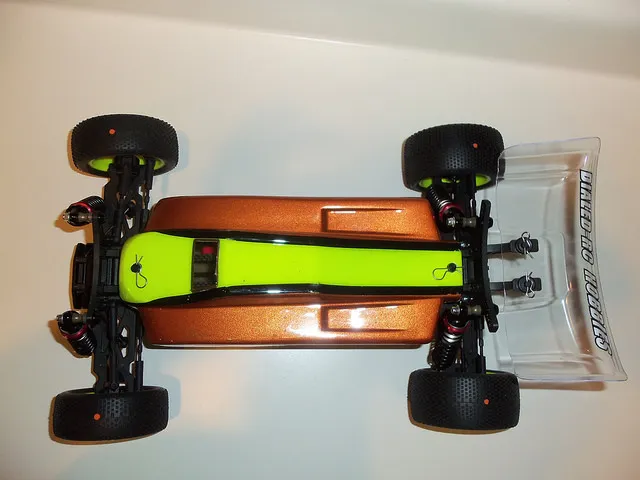
Build is complete, car is tuned and ready to race tomorrow!
After I get some track time, I'll post up a setup sheet. I drove the car around the house tonight and it turns VERY sharp... I can drive a complete circle within a 2.5' radius! I might have to dial back some steering... we'll have to see how she does.