IF14-II – Setup Explanation
- IF14-II - Setup Explanation -
Suspension Inserts
From Viktor Wilck
Update and explanation about new integrated item in IF14-2 car kit.
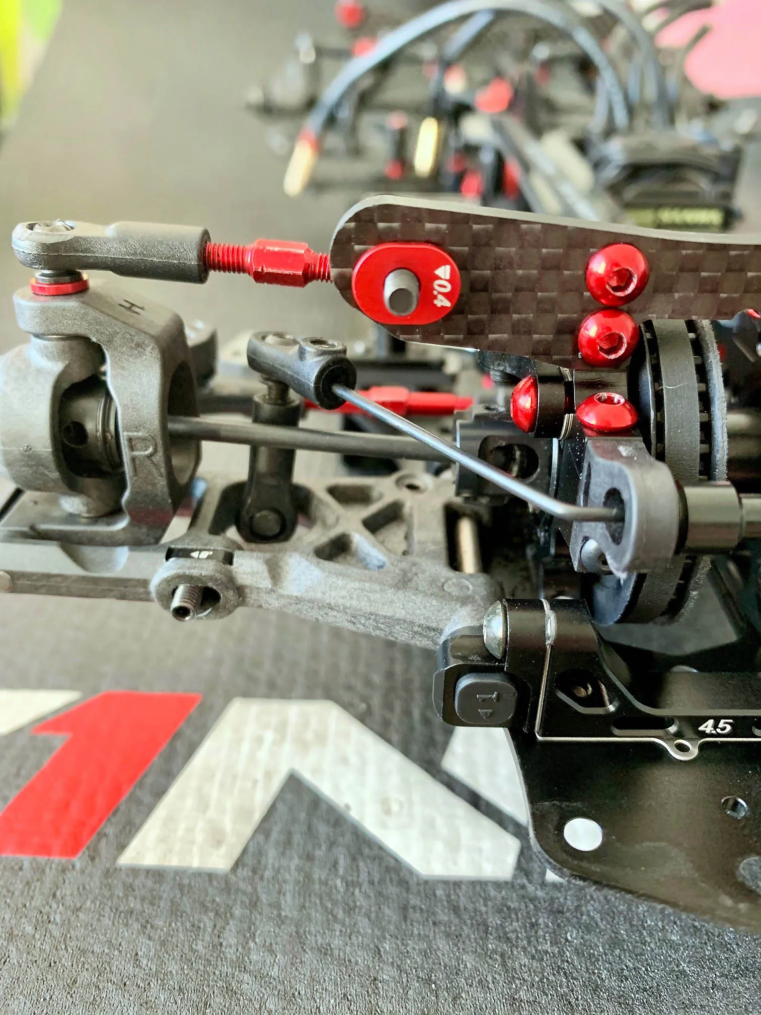
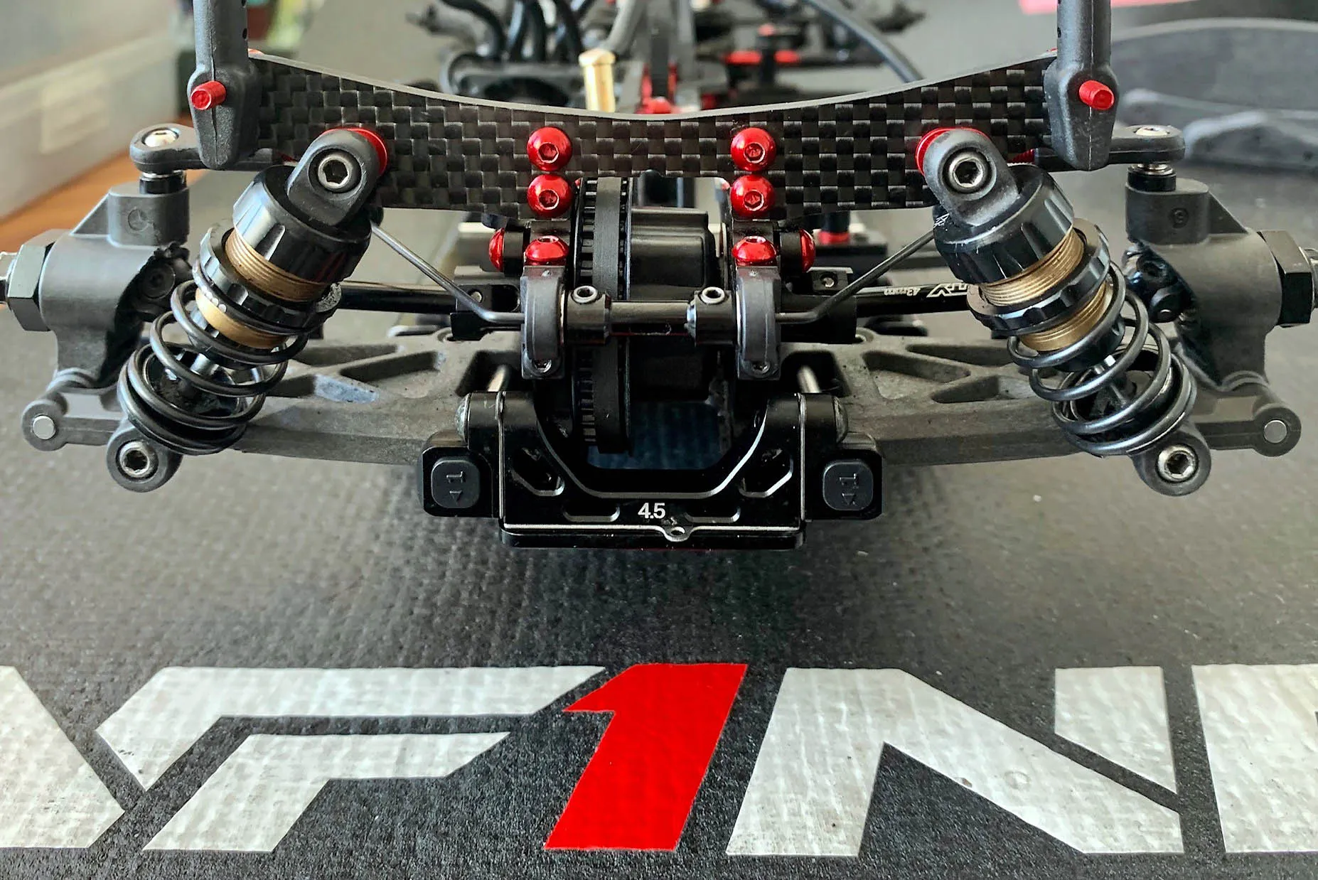
One of my favorite new setup option on the new car is the adjustable angle of the shocks with different inserts.
With these very precise insert you can fine tune you’re setup very easily with direct effect on the track. This is one the settings I changed a lot in TITC race and could fine very good balance of the car.
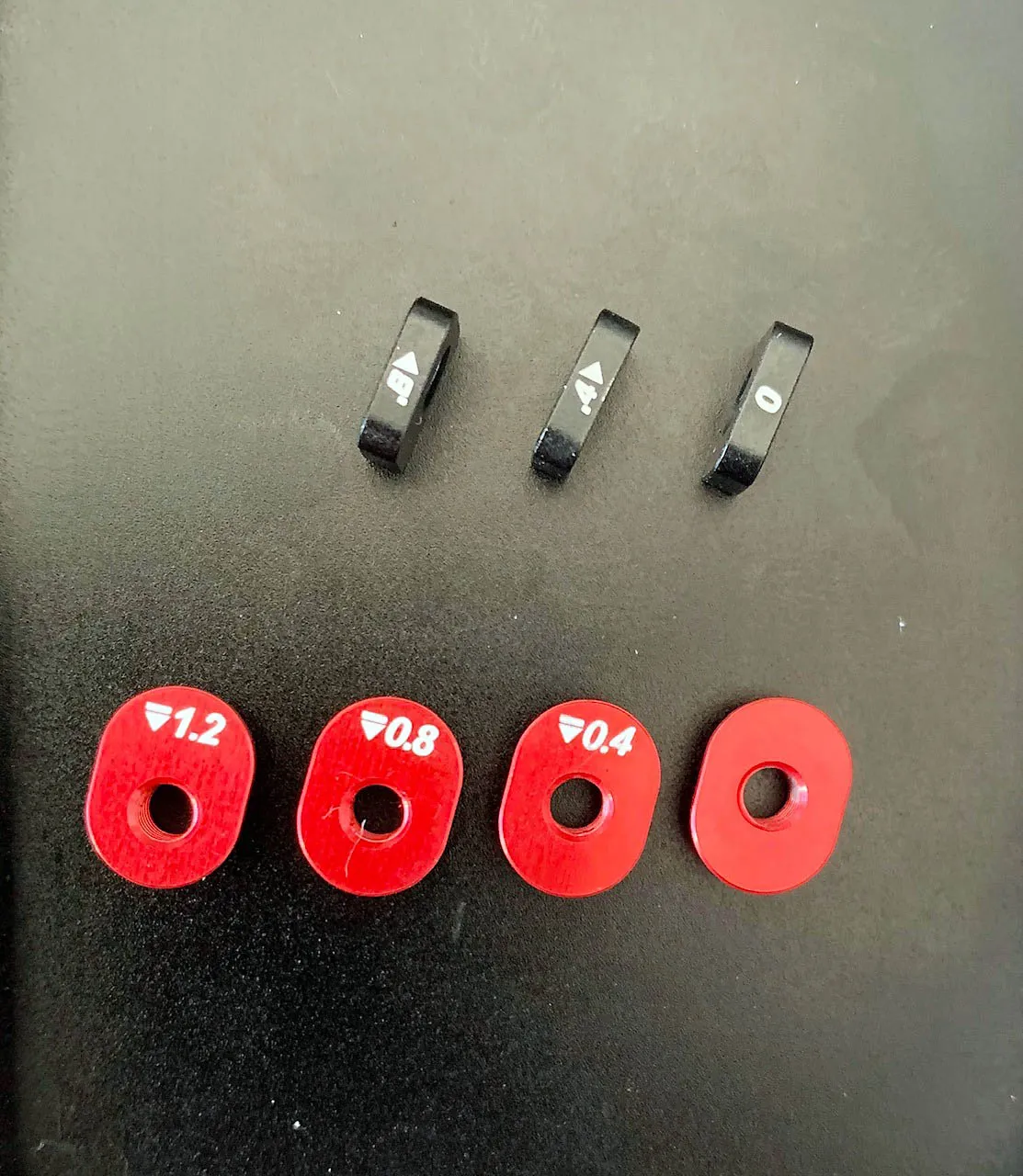
The upper mount (Alu Shock Mount Bushing) you can adjust the angle on the shock towers by 0 / 0.4 / 0.8 / 1.2mm
Part no
T222-0 0mm (include kit)
T222-0.4 0.4mm (option part)
T222-0.8 0.8mm (option part)
T222-1.2 1.2mm (option part)
My feeling Front shocks:
-> to the outside, more high speed steering, little less low speed steering
to outside, more stable on power
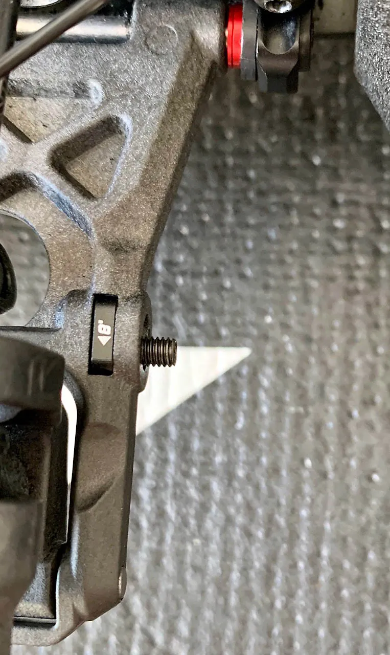
The lower mount (Alu Suspension plate) you can adjust the lower angle of you’re shocks on the wishbone by 0 / 0.4 / 0.8 / 1.2mm
Part no
T182-0 0mm (include kit)
T182-0.4 0.4mm (include kit)
T182-0.8 0.8mm (option part)
T182-1.2 1.2mm (option part)
My feeling Front shocks:
-> to the outside, more high speed steering, little less low speed steering
to the outside, less steering in low speed, but more rotation steering on power
My favourite settings in TITC race:
Alu Shock mount Bushing
Front: 0.4 -> outside
Rear: 0.4 outside
Rear: 0.4mm
Alu Shock Mount Bushing 0.4mm
Part no T222-0.4
Alu Suspension Plate 0.8mm
part no T182-0.8
Alu Shock Mount (red)
T222-0 0mm (include kit)
T222-0.4 0.4mm (option part)
T222-0.8 0.8mm (option part)
T222-1.2 1.2mm (option part)
Alu Suspension Plate (black)
T182-0 0mm (include kit)
T182-0.4 0.4mm (include kit)
T182-0.8 0.8mm (option part)
Screw setup IF14-2
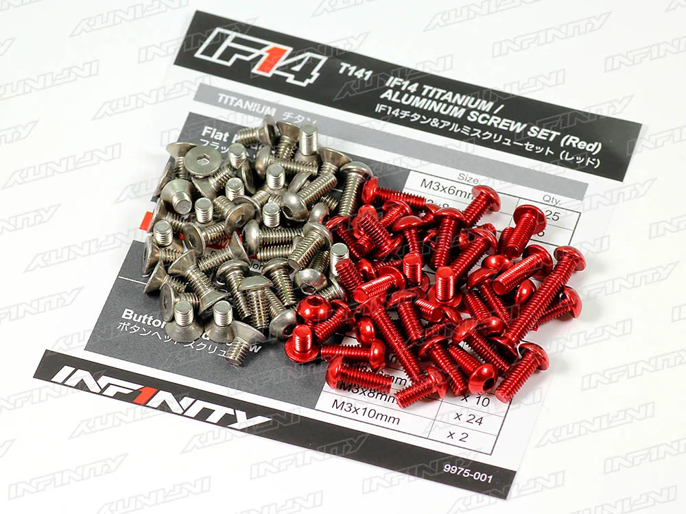
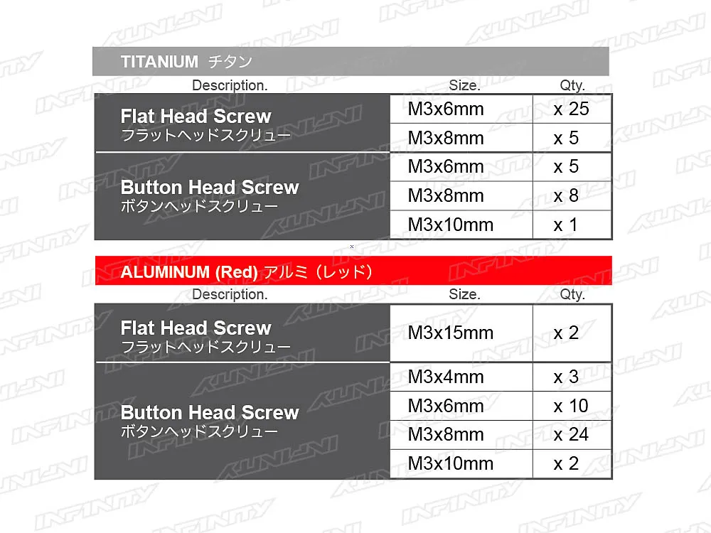
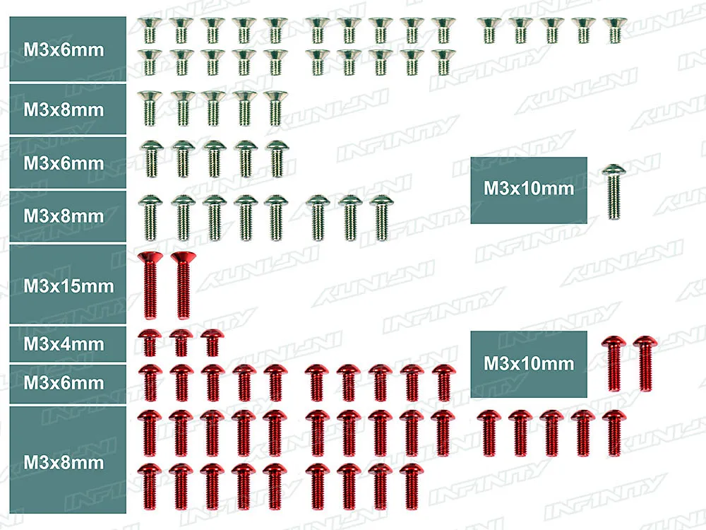
I would like to recommend different screws for your kit. Different screw can give different flex and weight of you’re car.
Mainly I use two different setups
Aluminum chassis
Top deck -> Aluminium screw red (option)
Chassis -> Titanium screw (option)
Carbon chassis
Top deck -> Titanium screw (option)
Chassis -> Steel screw black (kit)
Top deck
Most flex -> Aluminium screw red (option)
More flex -> Titanium screw (option
Less Flex -> Steel screw (kit)
Chassis
More flex -> Titanium screw (option)
Less Flex -> Steel screw (kit)
Part No
T244 - IF14-2 Titanium screw set
T246 - IF14-2 Titanium / Aluminum screw set (red)
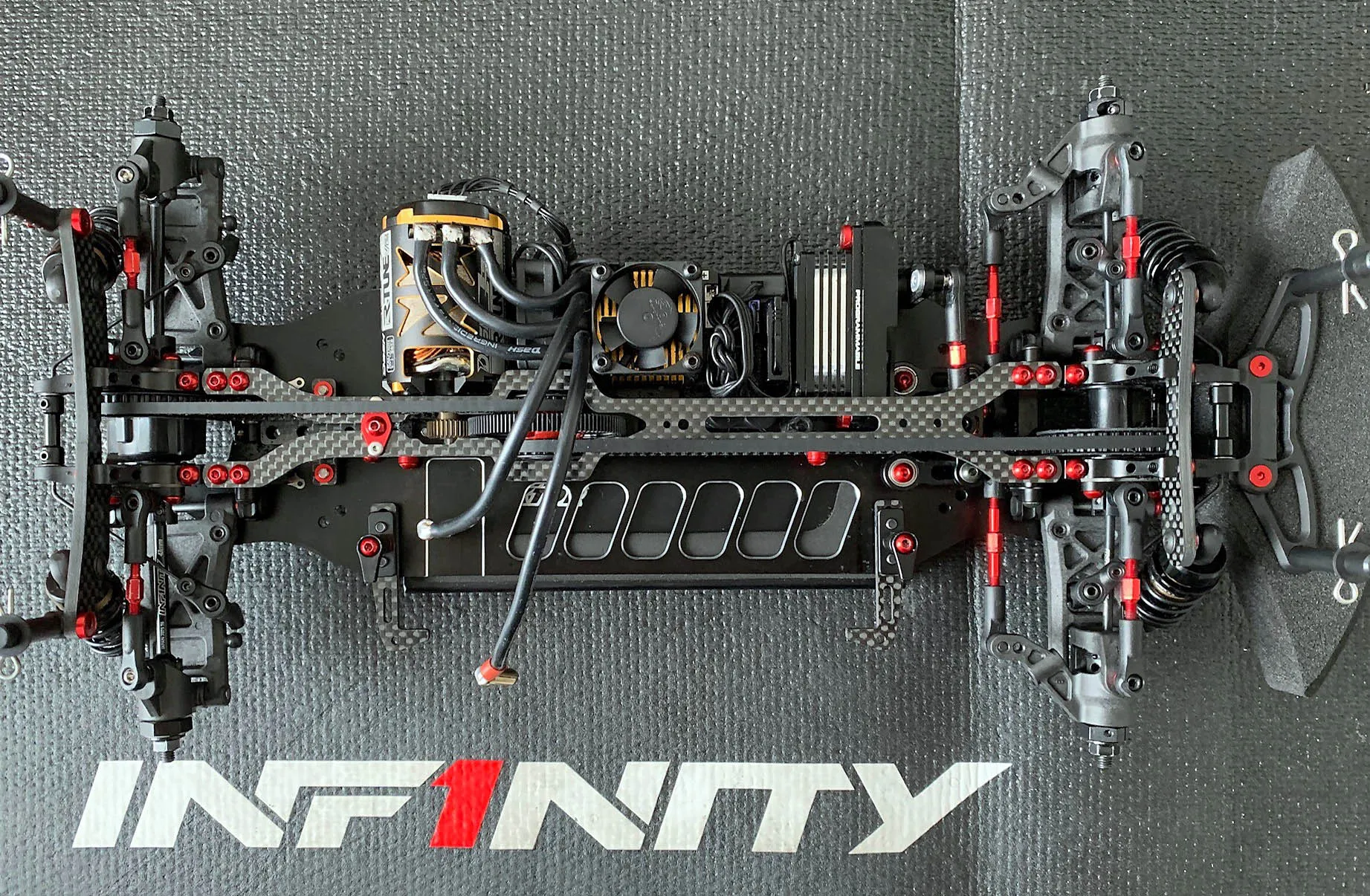
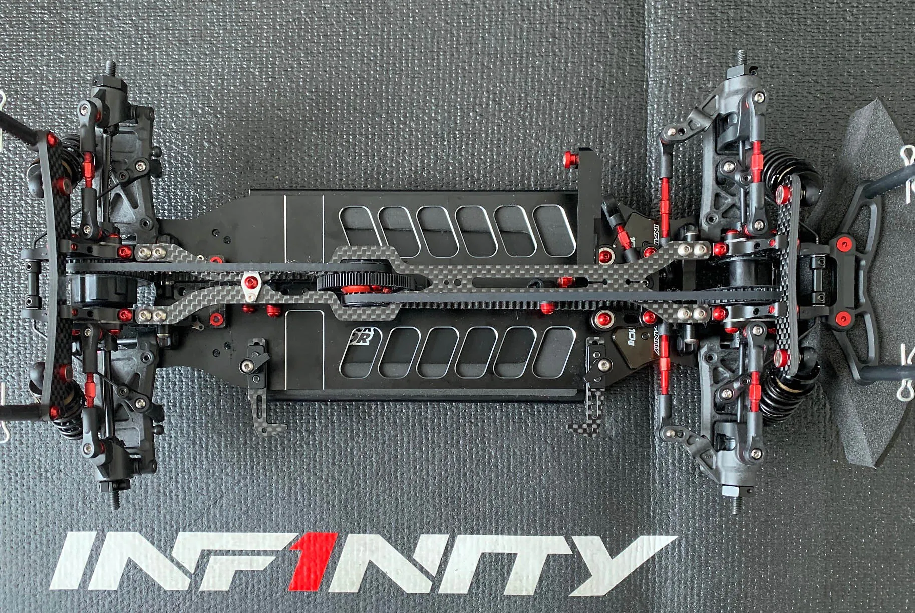
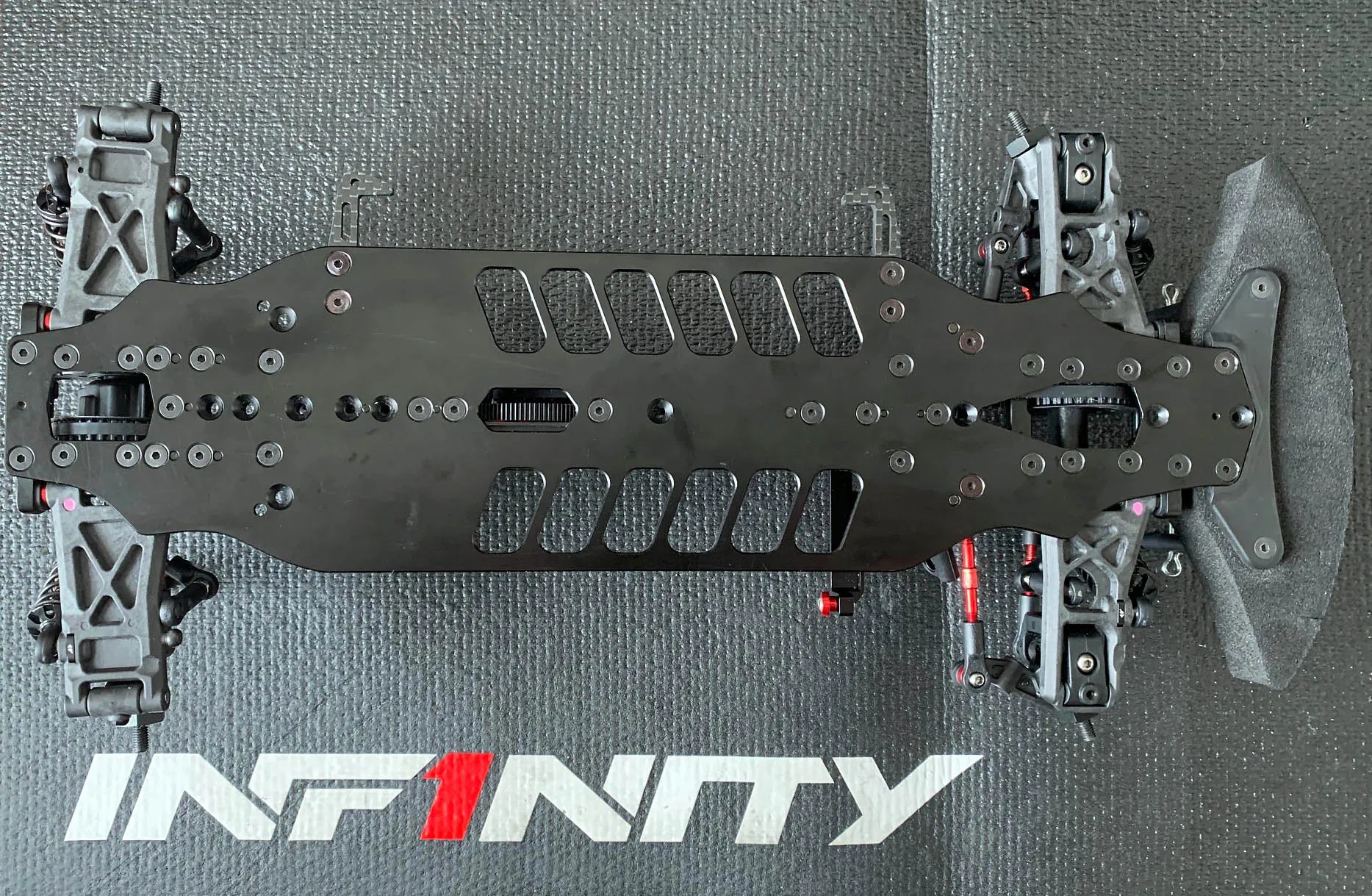
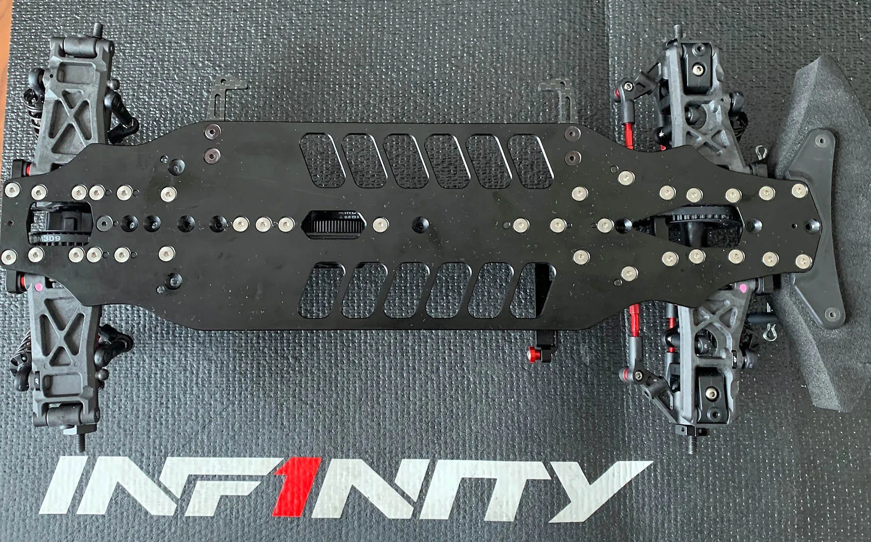
Aluminium & Titanium Screws
Explained by Jilles... where to use Alu ones, where to prefer the Titanium material... Steel screws to forget or we can use for different effects???
PRS / Passive Rear Steering
From Andy Moore
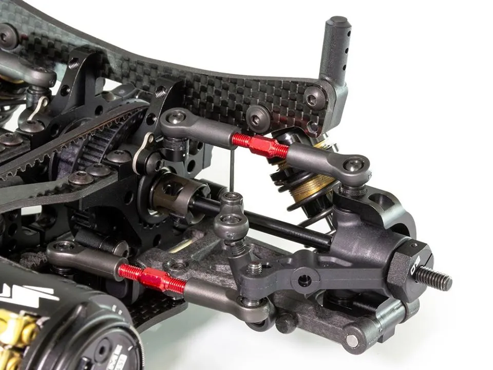
PRS stands for “Passive rear steering� and is essentially a system to increase, decrease or maintain static toe during the stroke of the rear suspension arm. The system uses a new aluminium C-Hub style upright together with a steering knuckle which is linked to a fixed position on the RF suspension block.
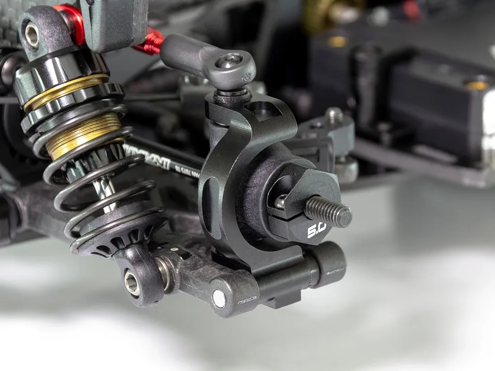
While the PRS system is usually best suited to high speed/flowing asphalt tracks it can also be tuned to suit all tracks and conditions.
How is it different to the standard rear end...
The slight increase in weight over the rear section of the car will generally increase the rotation and steering, while the angle of the link controls the amount of toe increase or decrease you are looking to achieve in a given track condition.
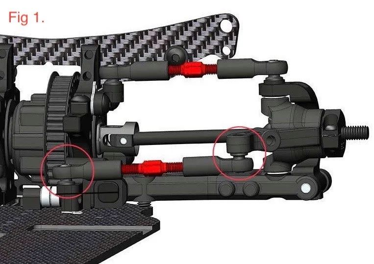
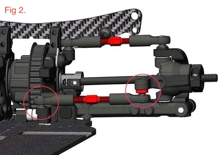
The pictures attached show the difference in link angle. In Fig 1 the link has more angle (no shims at the outside ball position) and will produce more toe increase and grip. Depending on track conditions this could allow for a more aggressive setup to be used. Fig 2 shows less angle (shims added) and will produce minimal toe change during suspension stroke and free up your car giving more corner speed.
Rear Chassis Flex
From Akio Sobue
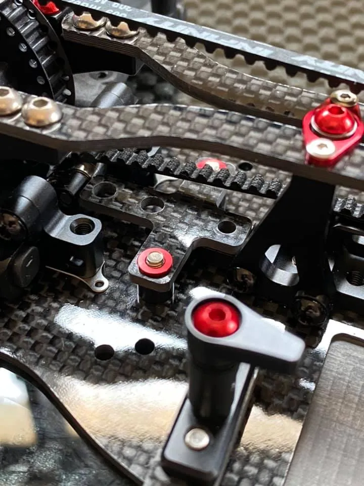
Rear side chassis flex will be held at "Graphite rear chassis extensions" equipped from IF14- 2.
The characteristics of this part with shape like cross can be adjusted to the horizontal and vertical chassis flex (Chassis Stiffness) each.
First of all, if you screw only 2 places same as the Morag Theory.
The chassis flex is suppressed, and the traction in the side is better when you put the power in it.
The next time you stop the screws, the traction will be better, and the kick to the front will be strong. The Rear Vertical Stiffness (Pitching Stiffness) is going up, so I tend to push the front tire.
And if you remove the graphite rear chassis Steph. The rear roll speed is fast, and the rear circling is fast for the start of the steering wheel. I think it's a valid setting in a lot of small corner course layout etc.
Finally, my basic set is only 2 in the side. We also remove motor mounts and fixed screws. This set is a good balance of traction and the balance of rear circling.
By changing the chassis flex around the rear in the setting of this graphite rear chassis extensions, the movement of the car changes greatly. Don't change the other settings, change the settings here and experience the changes in the car movement!
T-Brace Stiffener
Steering Plate
Suspension Blocks
Aluminium Spool Outdrives
Differential Break-In
Timelapse Chassis Change
Droop measure
Here two examples how to measure it. On our IF14-2 setup sheet you find two ways.
One is using regular droop gauge with 10mm blocks and you measure under the suspension arm( usually between 4 and 5mm in the rear).
The other way is to measure it with a caliper and measure from the ground to the middle of the pin. This measurement is 3.5mm difference with the same droop.
For example on our setup sheet you can fill in the droop measures under the suspension arm in the rear is 4mm. Then measured with the caliper from the ground to the middle of the pin it’s 7.5mm.
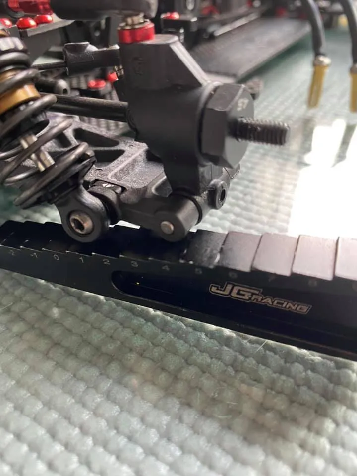
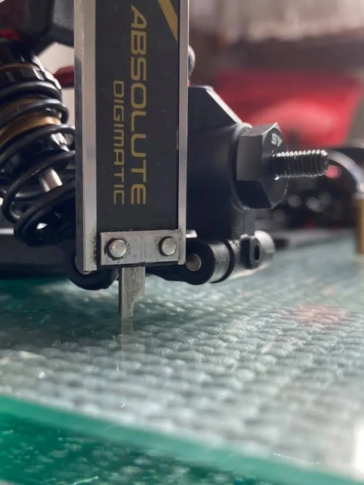
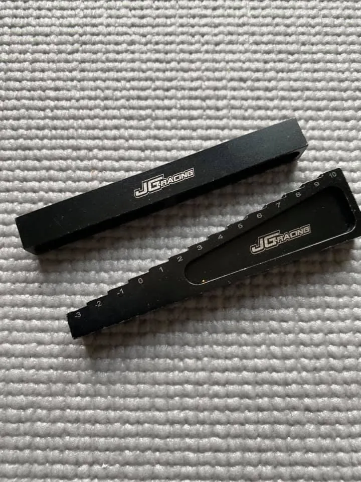
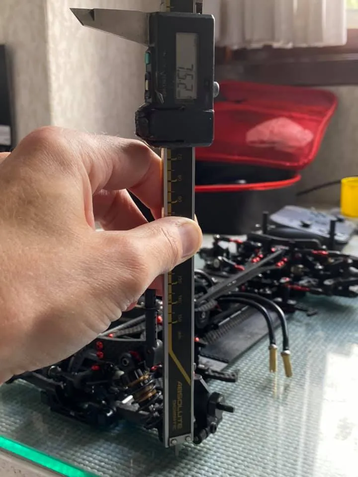
**Droop and Downstop settings shown and explained by Jilles Groskamp
**
Shock Assembly Tips
Shocks
Shocks Piston Position
Shocks Tilt Angle
IF14-2TE How to Build New USP2 Shock by Jin Sawada
IF14-2TE New Shock Build Tips by Naoto Matsukura
Layshaft Assembly
Graphite Front Body Post Support
Chassis Comparison
Floating Mount Holder
Balance
Graphite Options
Topdeck Tuning
Motormount
Ackermann effect
Shorty Battery Holder
Tweak Matter
HBP Body Mount Tips (#T265​-#T268​)
Adjustable Rear Horizontal Body Post Mount Set
Horizontal Body Post mount by Jilles Groskamp
Body Position
Setup Talks
Wheel Hex
Setup Indoor vs Outdoor
Belt Tension
By Kotonori Fujiwara
This time, I will add an explanation to the contents of the video, and I will explain the adjustment of the belt tension of IF14-II
In IF14-II usually, the tension of the drive belt before and after is adjusted by rotating the eccentric bearing holder (eccentric bearing holder) to a certain angle.
The tension of the front and back drive belt affects the throttle feeling and also affects the feeling of the whole car. How much tension you use the drive belt before and after is changed depending on the power source and driving style you use, so if you can adjust it, you can finish it to your favorite car. Yes.
In IF14-II countries, the front is an option and the belt tensioner is prepared, and you can adjust the feeling of the front drive belt by preventing the tension of the belt, and preventing the pokey at the time of the run.
However, as for the rear, you can only adjust the tension with the eccentric bearing holder, and sometimes you can't adjust it to your favorite belt tension.
What should I do in that case?
Rear belt tensioner is equipped in front of rear def in IF14-II But this tensioner has no tension adjustment mechanism.
But you can use this tensioner with a little idea to adjust the tension of the rear drive belt.
Eccentric Bearing Holder adjusts somewhat belt tension to loose condition. And between the rear belt tensioner and the main chassis, the rear belt tensioner position is high across the sims of the 0.2 mm. This is how you can get excited about the rear drive belt, and you can adjust the tension of the rear drive belt.
At this time,
T199-0.2 Lower Suspension Block Spacer 0.2mm
If you use it, you can adjust the rear belt tension without removing the rear belt tension, and it is convenient.
However, when the rear belt tensioner position is too high, the refraction of the rear drive belt is getting bigger, and the powered loss is getting bigger. Under the rear belt tensioner, the sims are about to be a mm ~ a mm.
The drive belt is the character of the product, and there is an error in the belt length.
Even the same length belt is slightly different depending on the production lot, etc.
(this is not faulty, it is inevitable for product manufacture)
Also, the drive belt will grow slightly by running, so please make sure to check it out again after a certain amount of run.
A Solid-adjusted drive belt is a good driving feeling, and it's long lasting without a tooth fly.
The tension of your IF14-II drive belt, please adjust this for reference.
Graphite Brace
Top Desk Tip
SMJ Weight Balance
Steering Angle & Toe Out
Steering Angle by Viktor Wilck
Quick Maintenance
Optional parts by Viktor Wilck
Setup talk by Jilles Groskamp
Alu Adjustable Servo Horn by Jilles Groskamp
Carpet Settings by Viktor Wilck
Carpet Setup by Jilles Groskamp
USP Graphite Flex Shock Tower
Camberlink setting on high bite surfaces
Camber Change
Wing position
Bodyshell Choice
Motor mount options
Axle height tune
IF14-II TE Axle height tuneWheel Axle Height Adjustments
IF14-II T-Brace Options
IF14-II Bumpsteer
HARD vs SOFT Shock Membrane
-
T070 INFINITY IF14 Shock Membrane (4pcs)
-
T070S INFINITY IF14-2 Shock Membrane (Soft/4pcs)
HARD Vs GRAPHITE Upright & Steering Block
-
T123 - Graphite Upright
-
T122 - HARD Upright
-
T121 - Graphite Steering Block
-
T120 - HARD Steering Block
IF14-II Long Vs Short Wheelbase
Build Tips - Turnbuckle
Passive Rear Suspension Vs Standard Rear Suspension
IF14-2TE Steering Block Spacer by Jin Sawada
IF14-2TE Steering Block Spacer by Jin Sawada
IF14-2TE Mid T-Brace setting by Viktor Wilck
IF14-2TE Mid T346 by Viktor Wilck
IF14-2TE Mid Setup Tip Suspension Block by Viktor Wilck
IF14-2TE Mid Setup Parts by Viktor Wilck
Shock Rebound by Viktor Wilck
Spur gear size for different motor position