Rapide F1 EVO3 – Assembly Review
- Roche F1 Evo 3 Build -
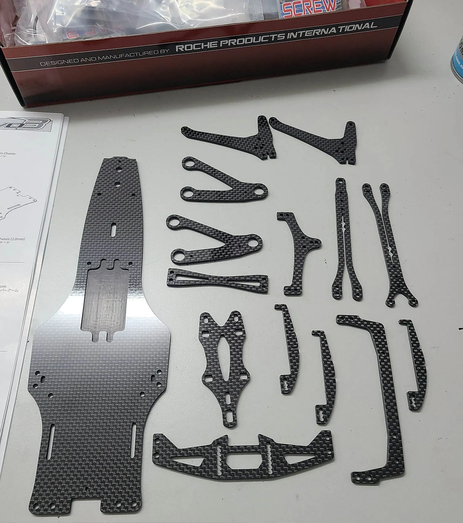
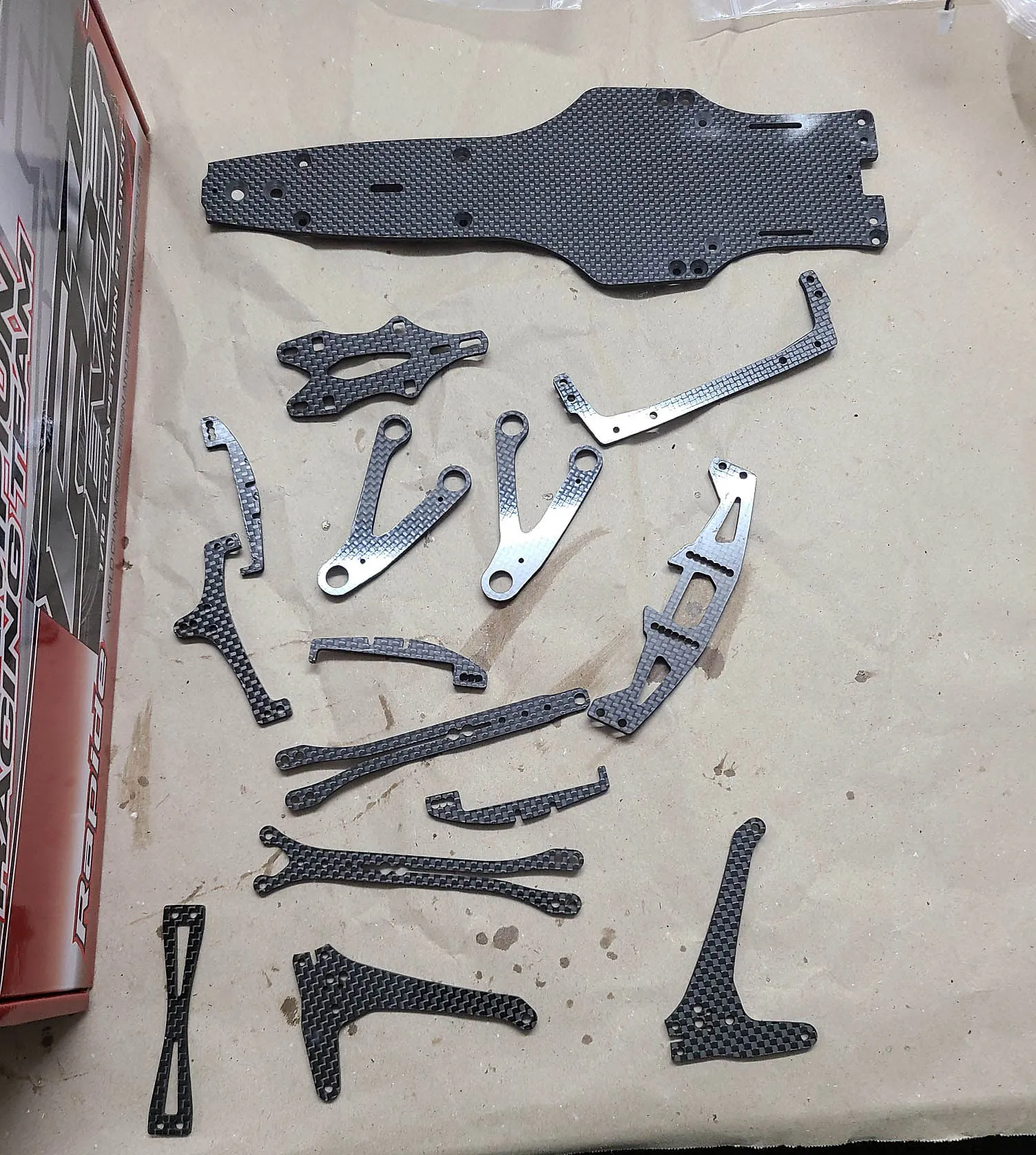
Episode 1: The first amount of pictures show the preparation of the Carbon parts and the sealing of the sidewalls. I added some text to every picture with small tips and how I do the current step.
The first amount of pictures show the preperation of the Carbon parts and the sealing of the sidewalls. I added some text to every picture with small tips and how I do the current step.
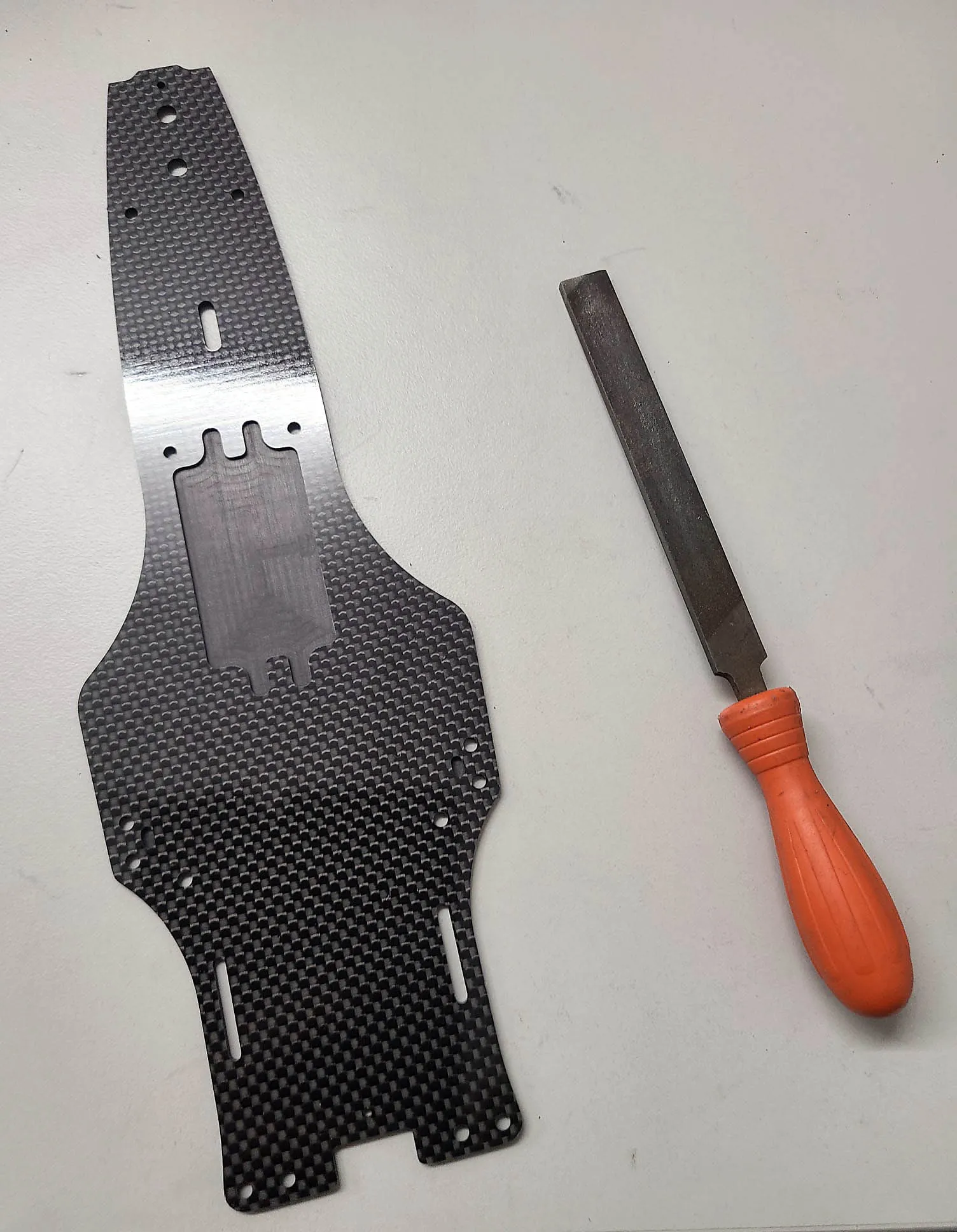
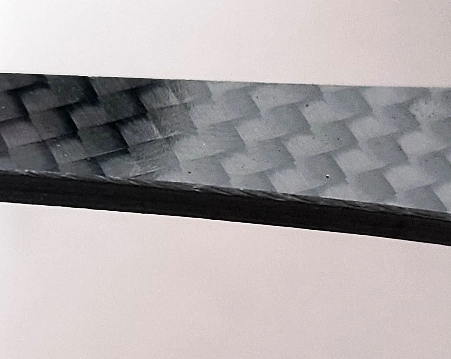
Now I prepare the Chassis and other Parts with a file to break the sharp edges of the Carbon
Its important do to it from each side of the part
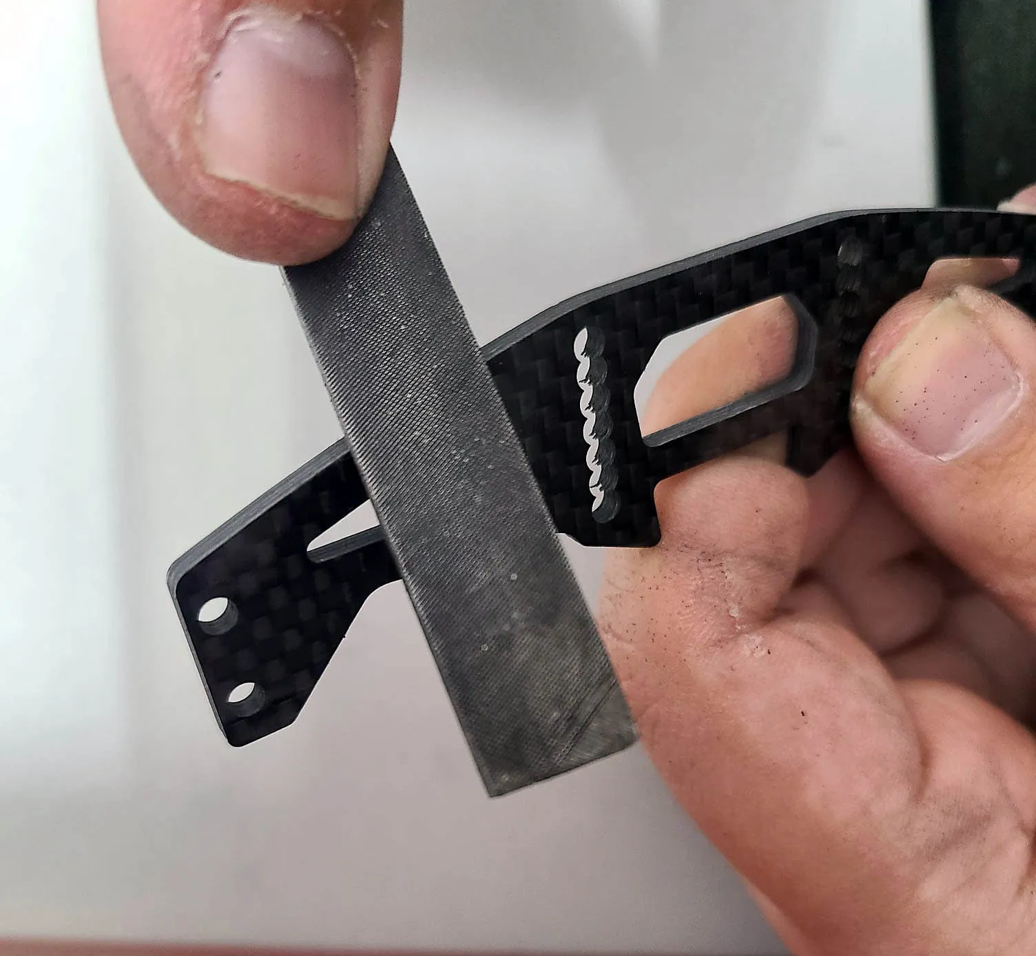
Here is a picture with a sharp edge directly taken out of the Box
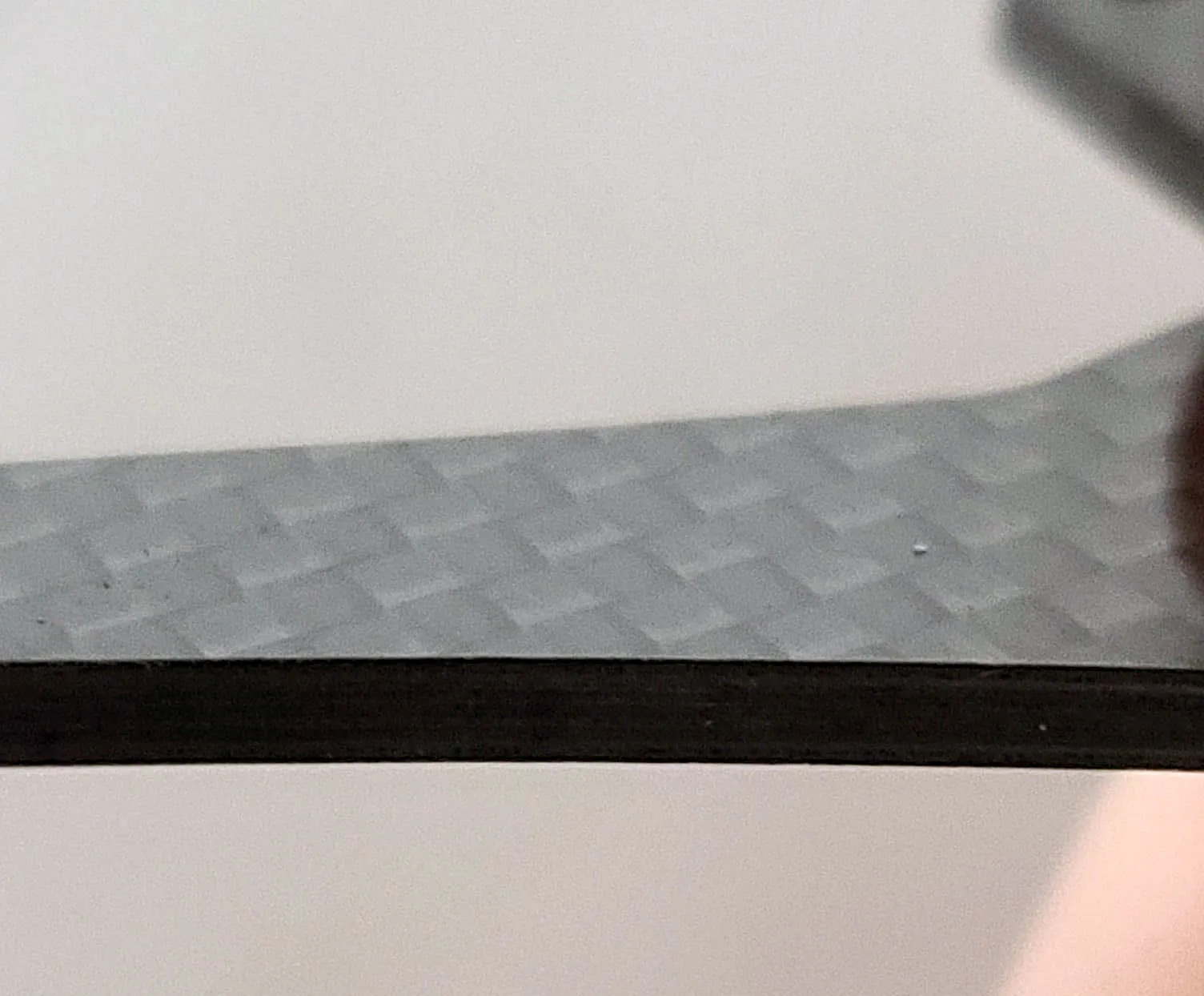
This shows the same part after grinding
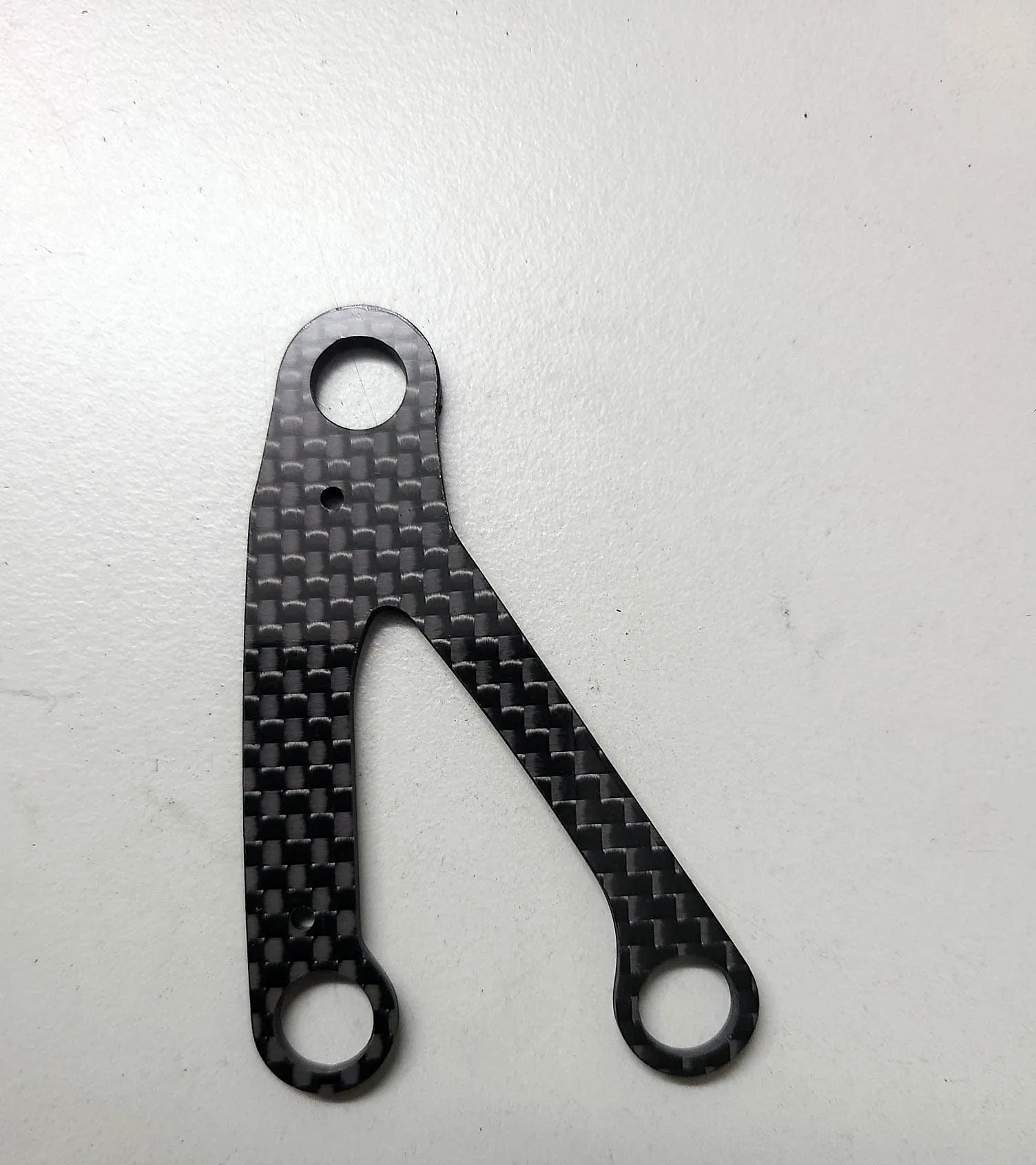
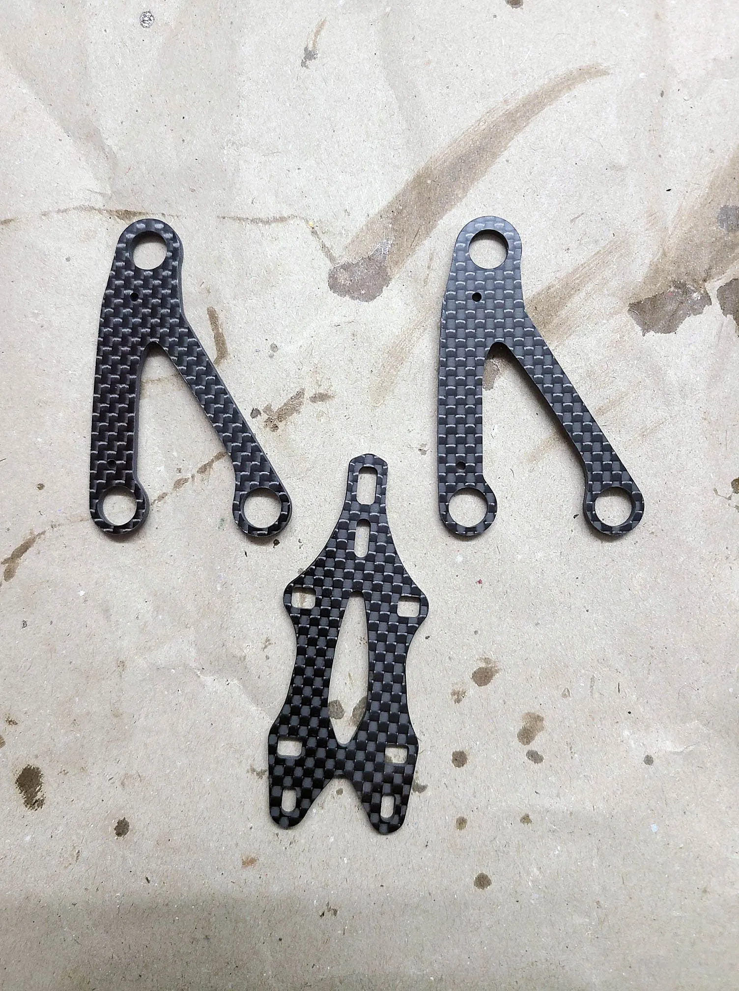
I recommand to not sand the holes of the top arms for now. The holes are quite good for putting in the plastic insert with the balls
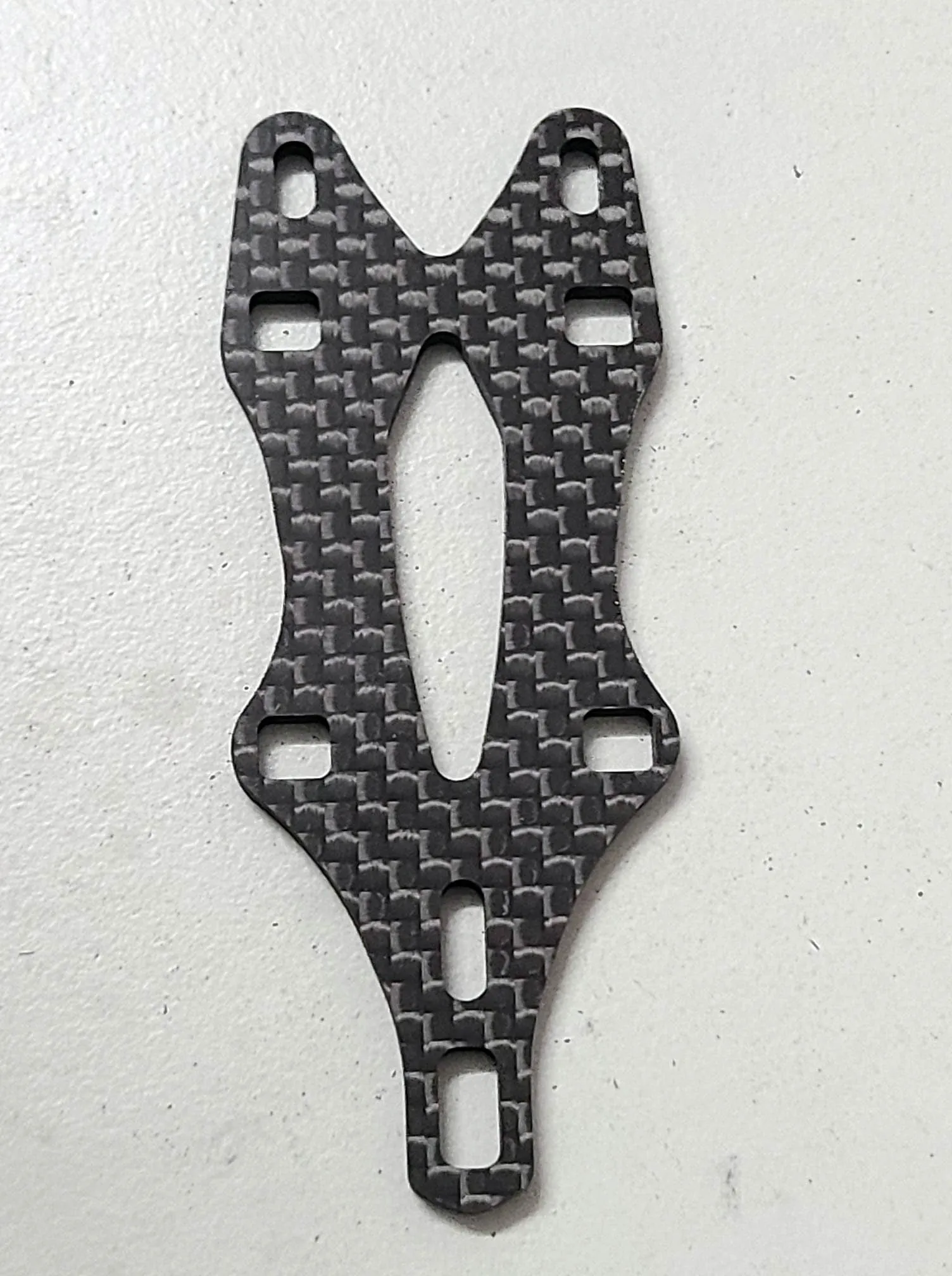
We have the same situation with the top plate only grind the outside but not the holes for the camber and caster inserts. The cut-out in the middle can be sanded too
Take care and clean your hands after sanding. Carbon dust is toxic and thats why I clean every side of the carbon parts with brake cleaner
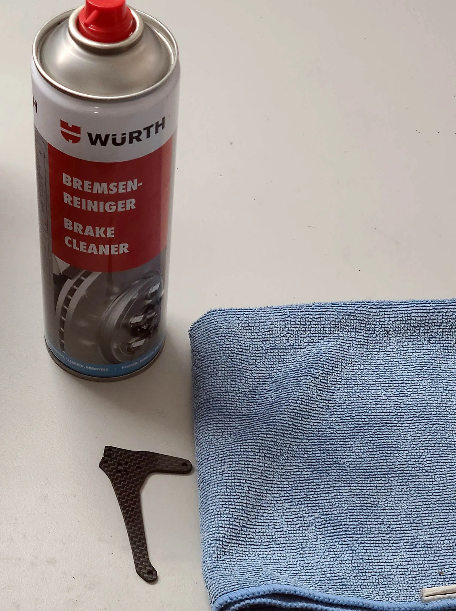
I'm using a small amount of brakecleaner on an cloth and clean every side
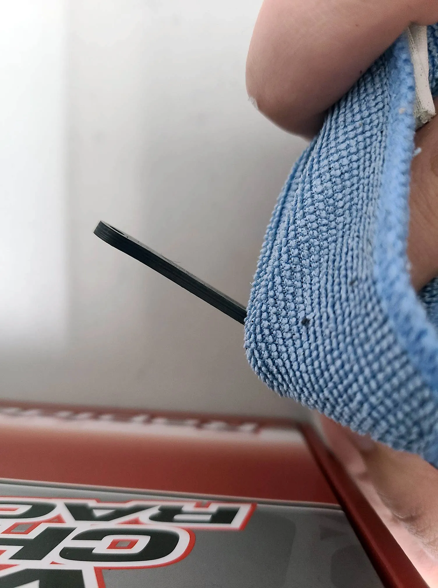
Next step is to seal the sidewalls of the carbon. I always use clear coat and not super glue for sealing
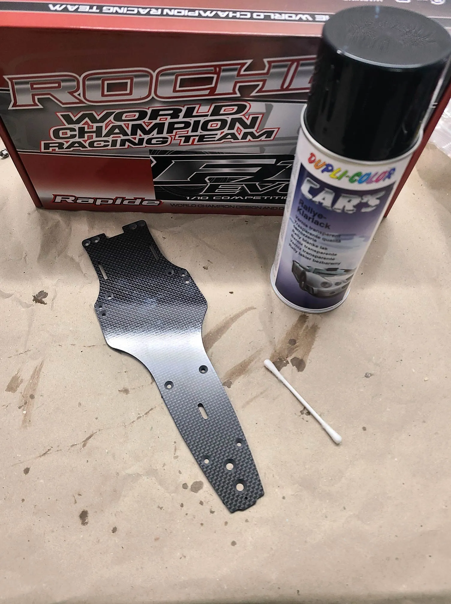
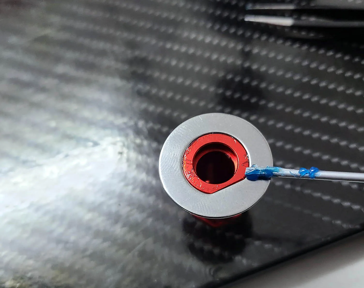
I recommand to use a Q-Tip for apply the coat. Its easy to handle and will not generate drops.
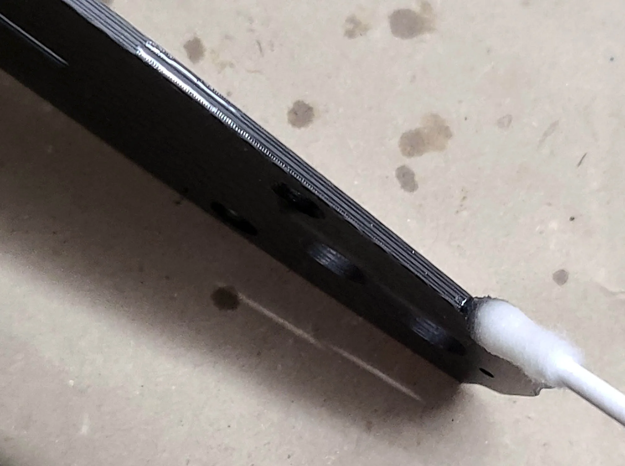
I even out a small amount of coat inside the countersink of critical holes. Here I put the coat inside the countersinks of the lower arm mounts
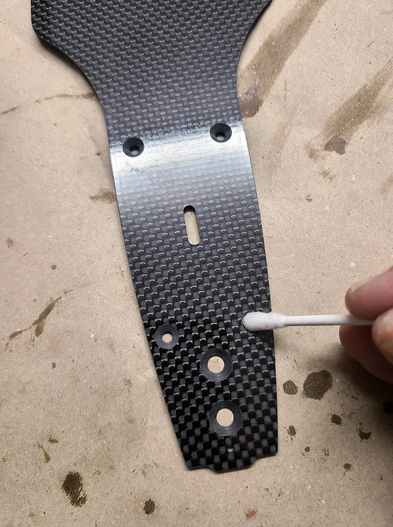
Tip from my side put coat inside the countersink of the link mounts. This will help to get them in place. I recommand to do the same with holes for the post and the wing to chassis plate.
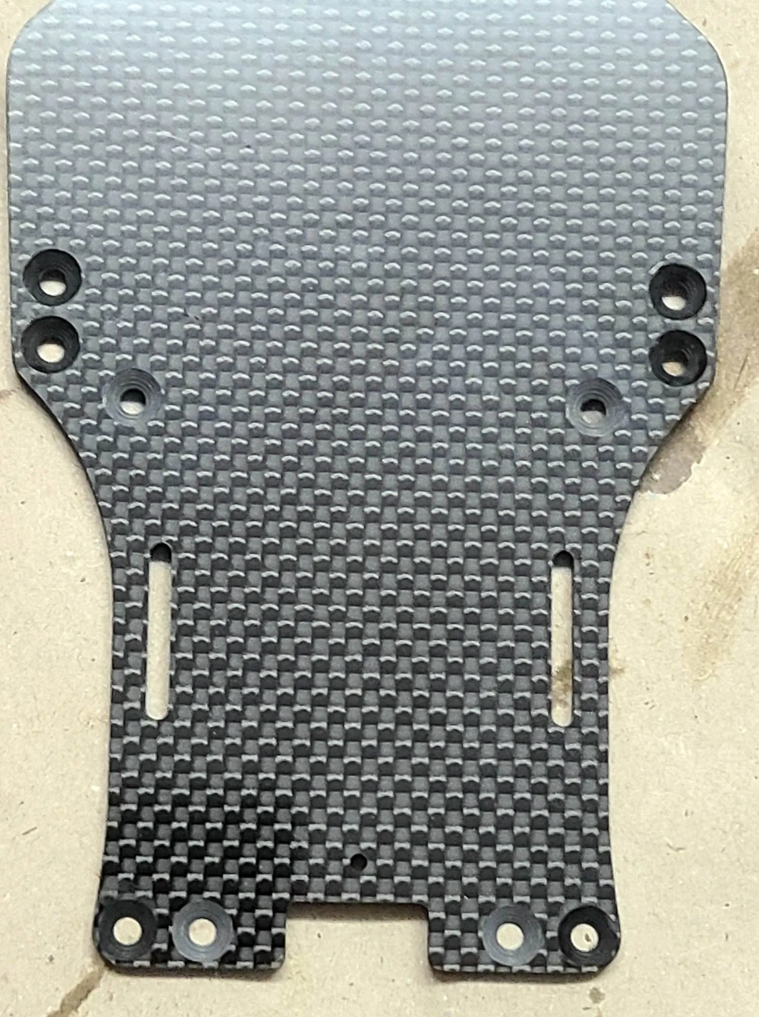
I suggest you to not seal the the holes from the top arm. If you do it makes the holes more tight and can lead to binding. A Similar problem you will get when you put coat in the holes for the camber and caster inserts. So try to avoid putting coat inside these holes.
Last thing is the most boring step. We have to wait till all parts are dry.
Episode 2: Today we start with the build. The first steps are pressing the balls inside the plastic inserts in the correct way and fix a small amount of binding
For putting in the balls inside the inserts I can recommand you to use a multi tool like I you can see here. I put the ball onto the small post and the plastic part on the oppsite and last but not least I press the tool together and get in the ball very smoothly
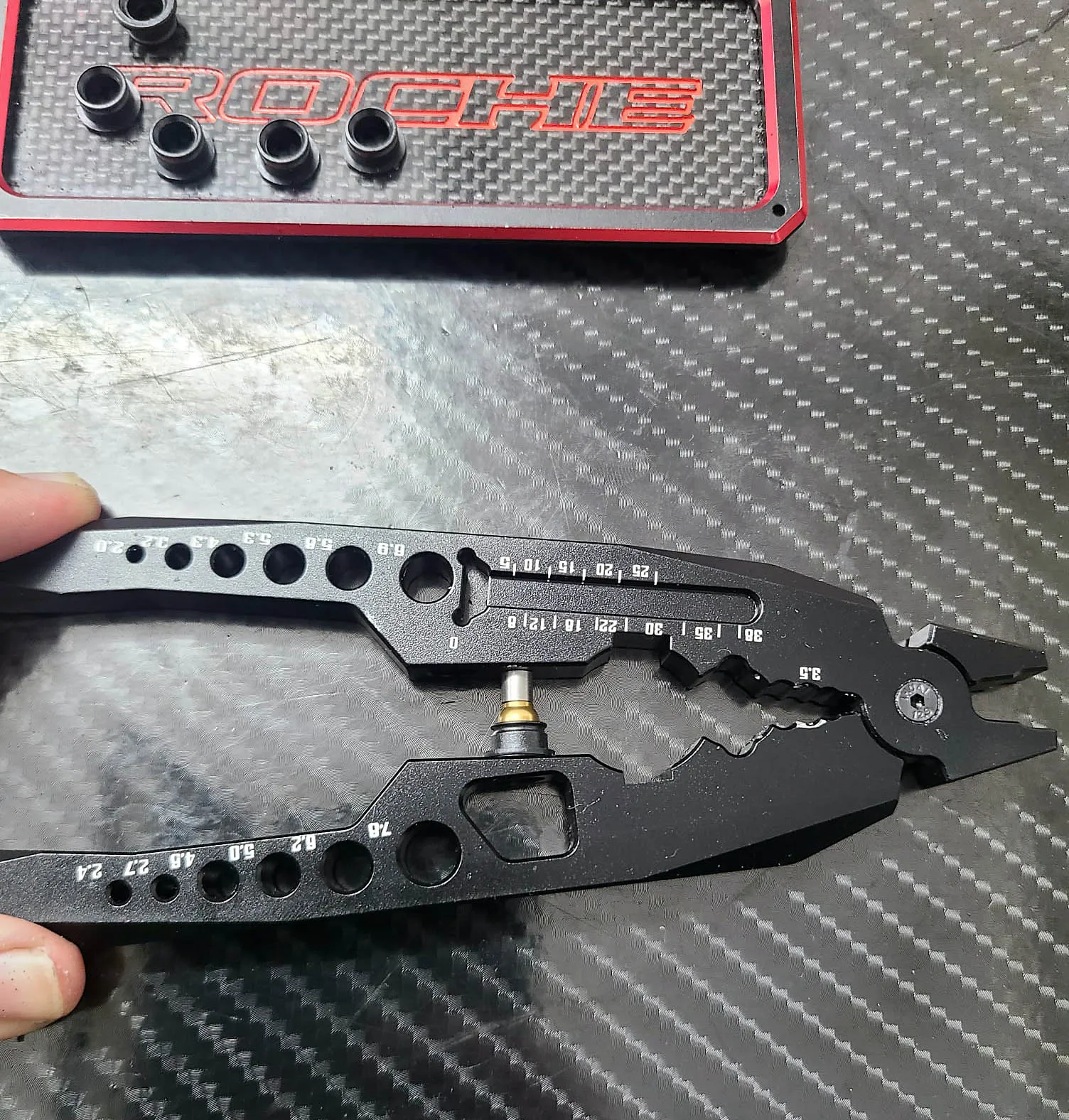
Its the same procedure for putting the ball inside the lower arm ball cup.
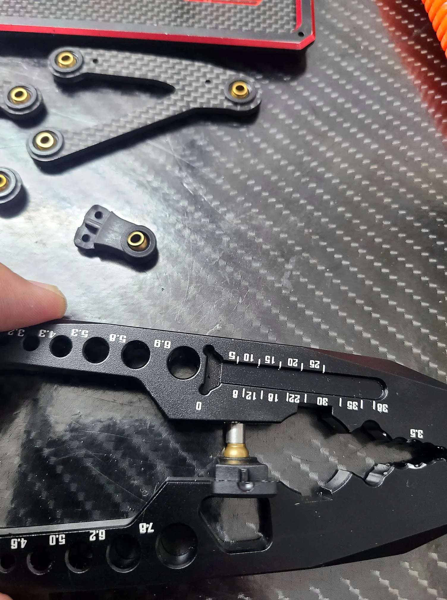
I suggest you to check every insert with a ball inside if it moves freely. A normal screwrdriver wil help you to find it out.
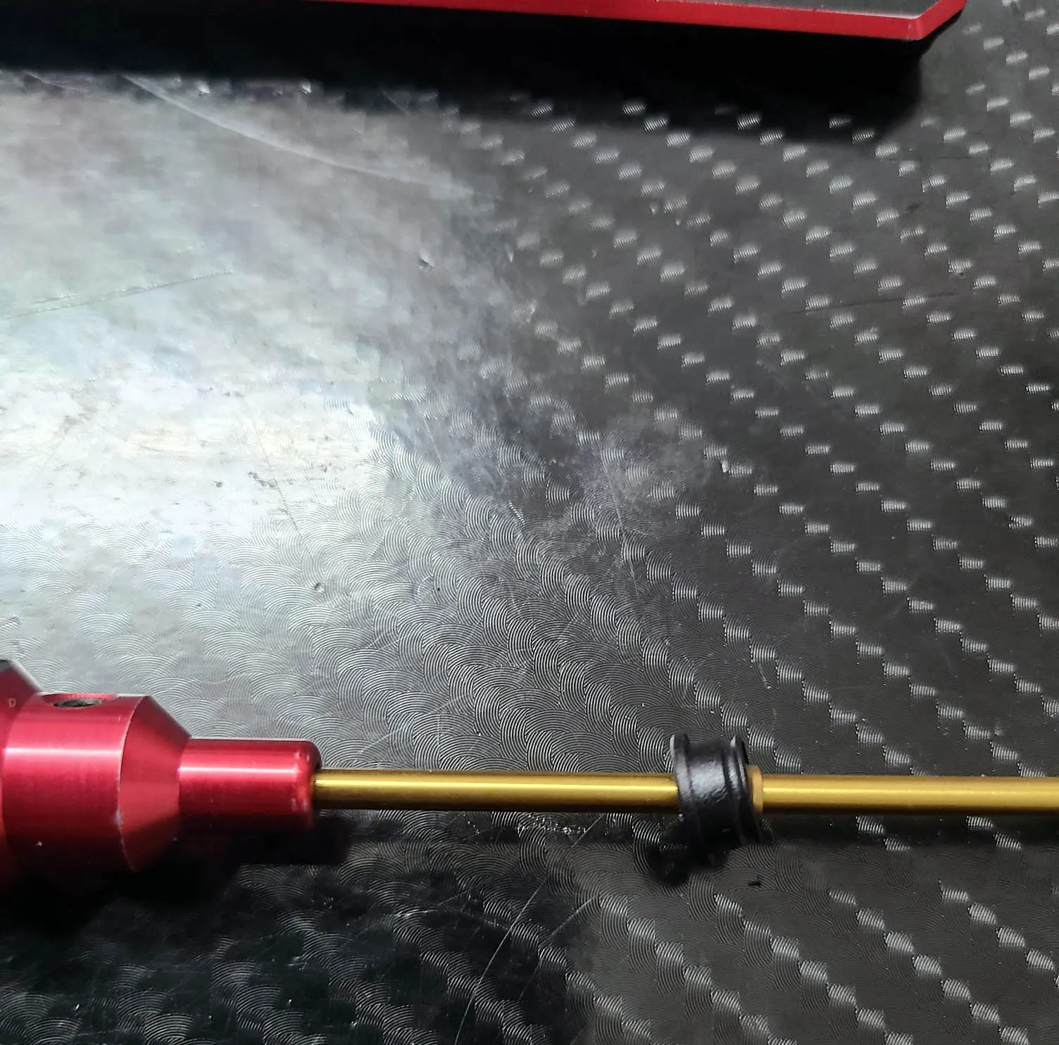
In case you have some binding or it does not feel smooth I use the multi tool and press the insert together very slightly. It will help to get the ball into the right place without destroy the plastic.
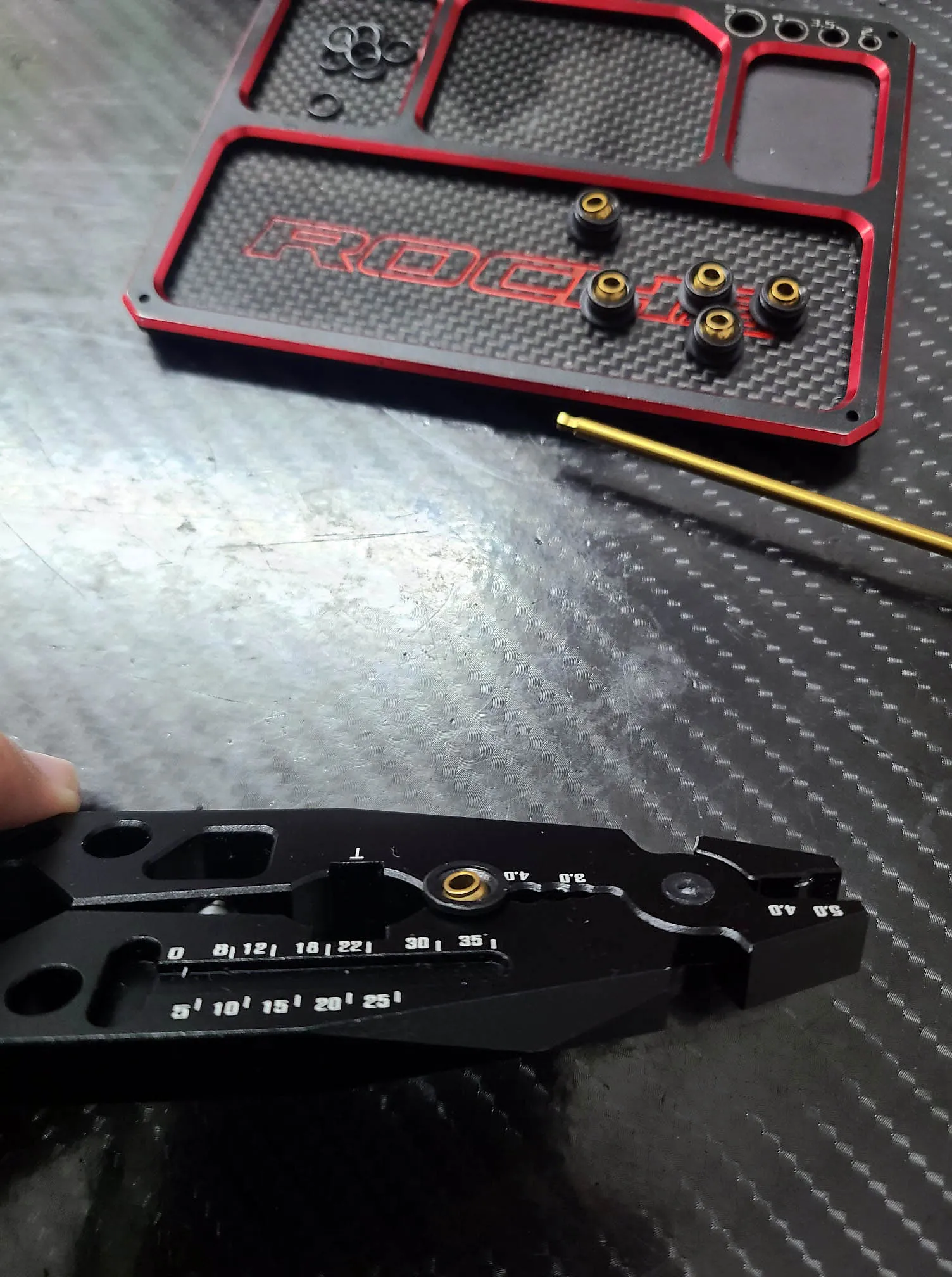
Double check if the ball moves freely after inserting it to the top arm.
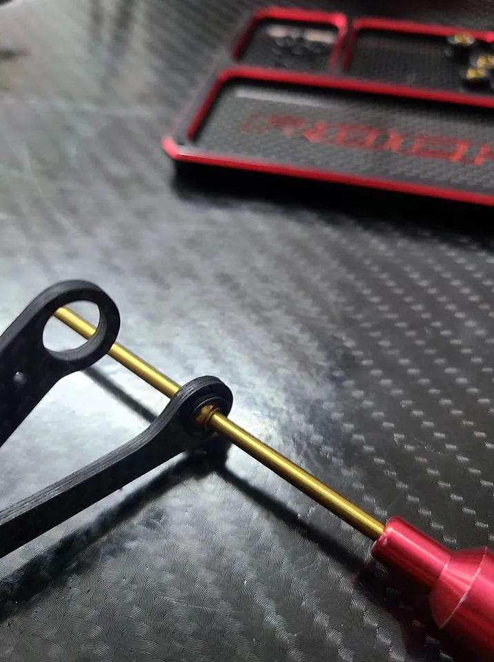
If you have noticed some balls are not moving freely push the insert out of the arm and search some sandpaper
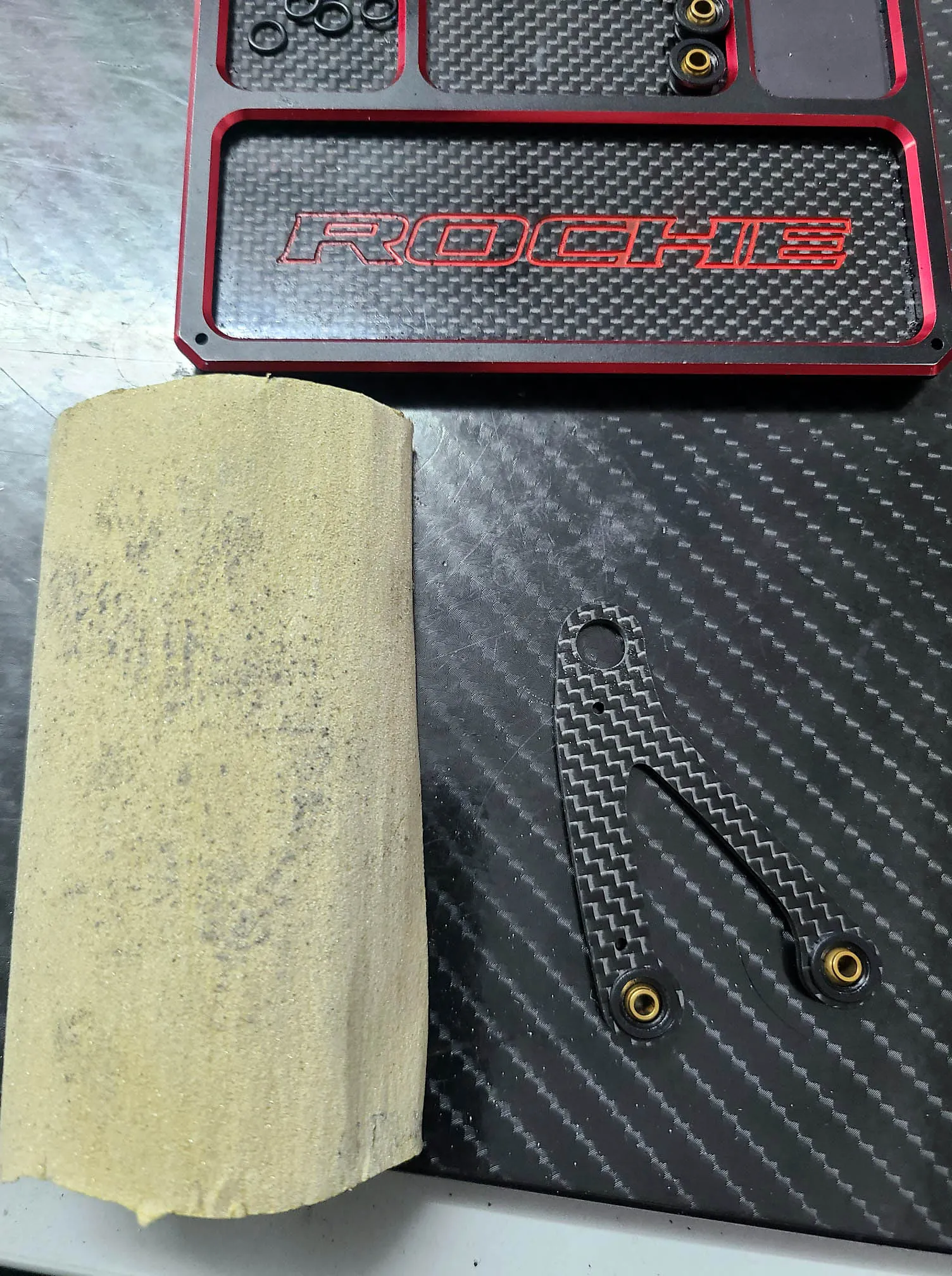
After you take the sandpaper roll it up and put it into the critical hole. Just turn the sandaper a few times and the binding will go away.
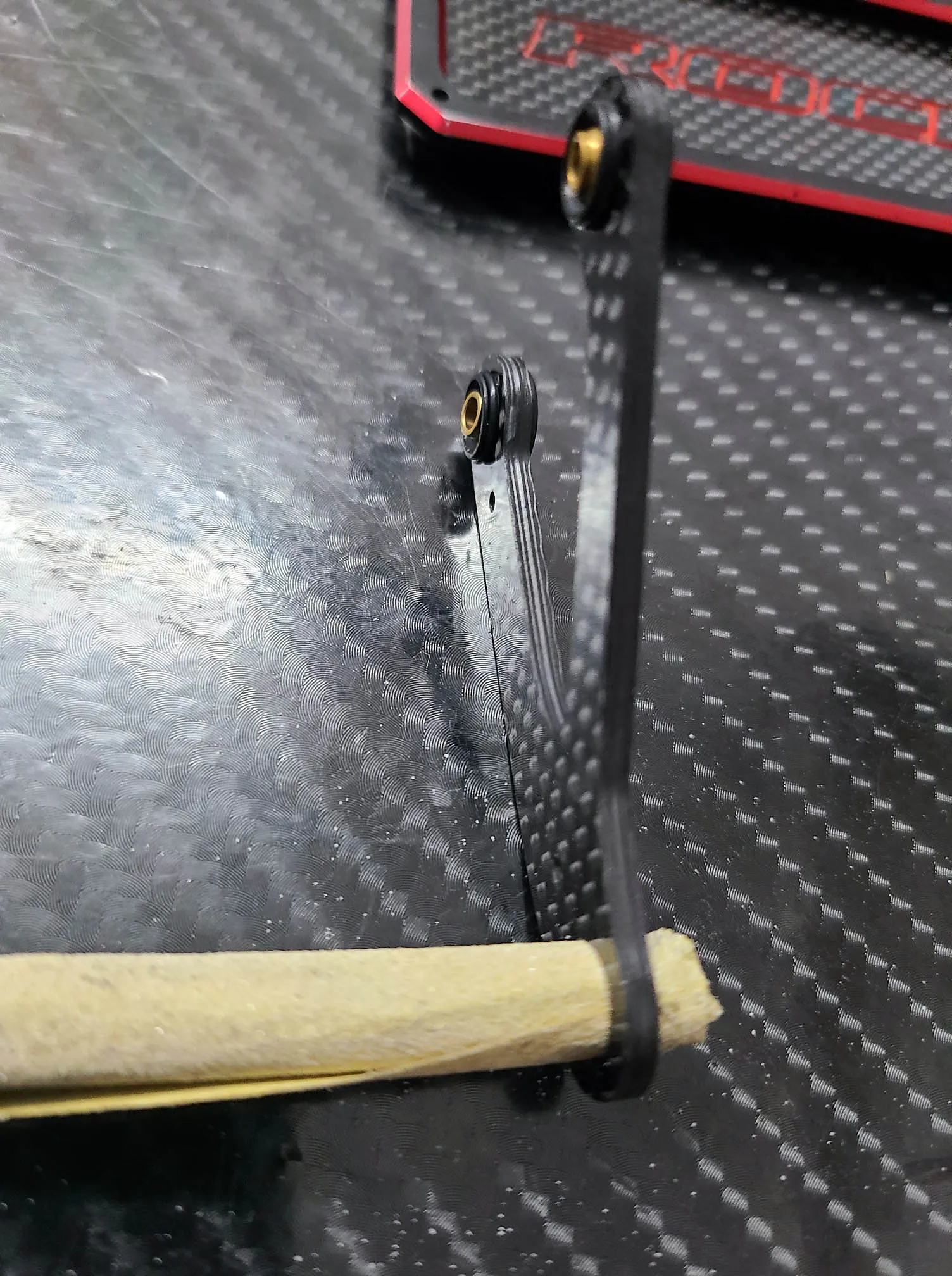
Repeat the step till you get free and smooth movements of every ball.
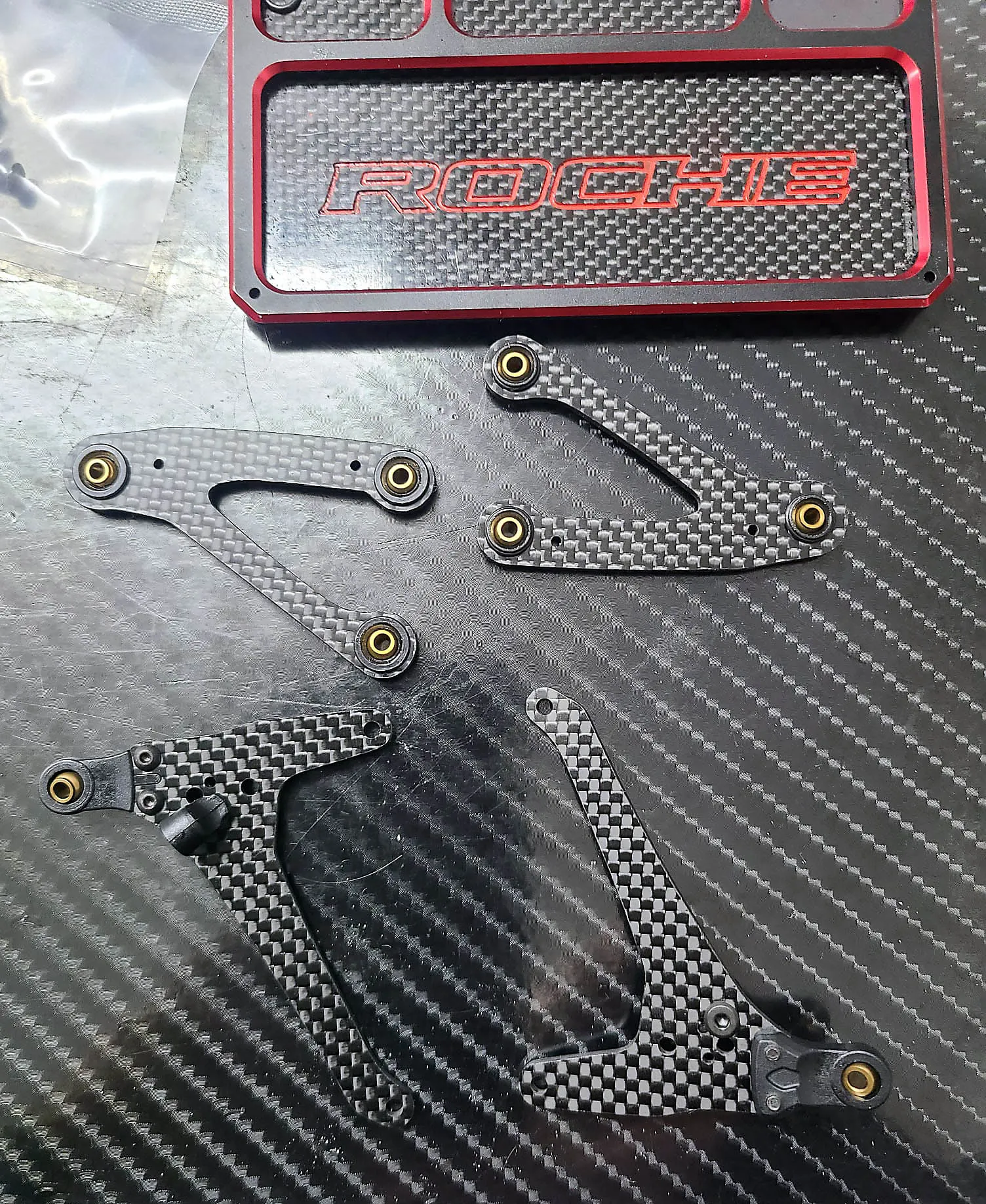
Episode 3: The Topic this time are the steering arm and the setup options for the lower carbon arm
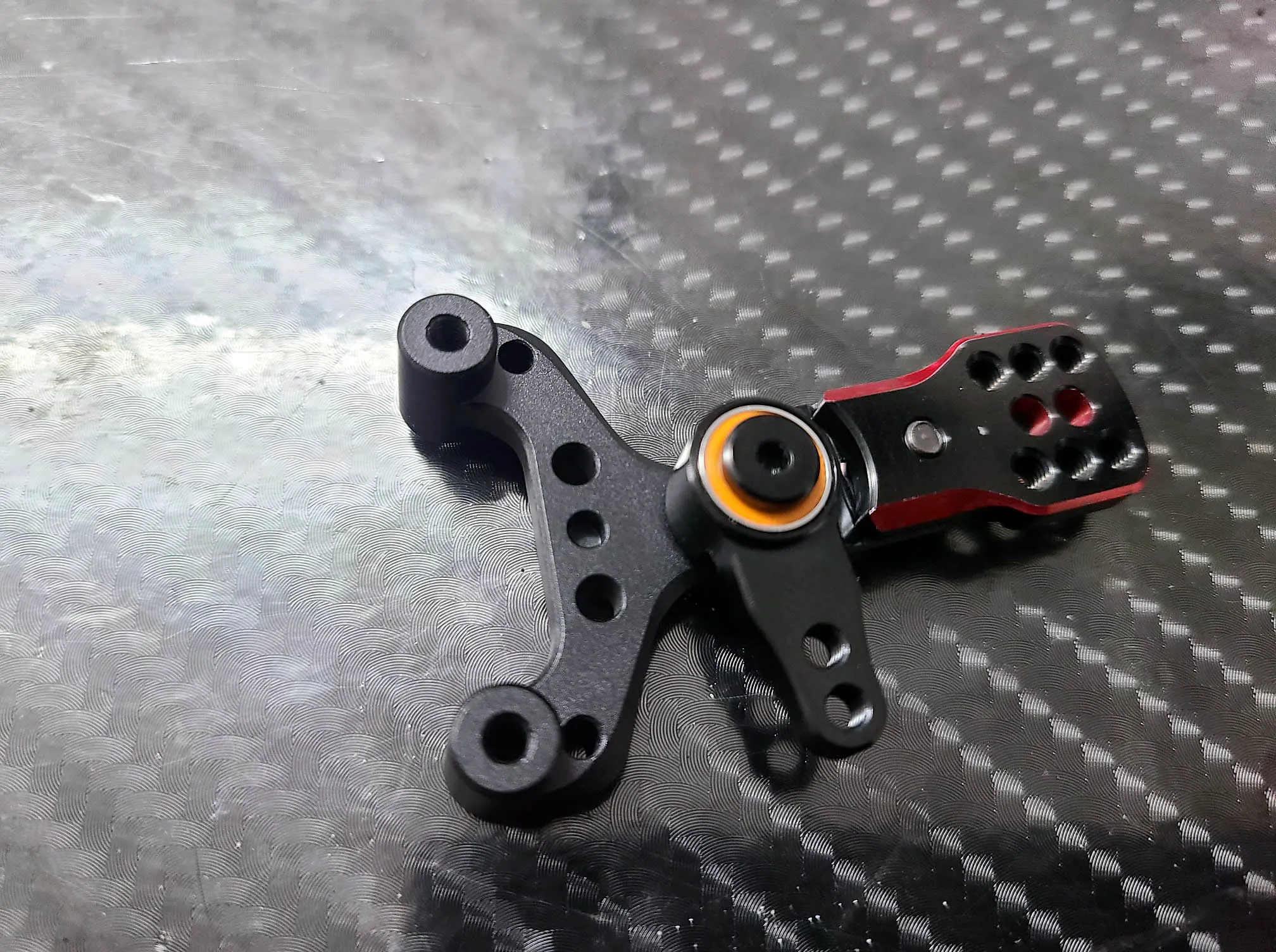
This optional Steering arm set is a must have. It looks better than the orginal plastic part and due the new design and ballbearing inserted from factory it has less play than every other option. Another good thing about this part it has two extra holes for better ackermann adjustment
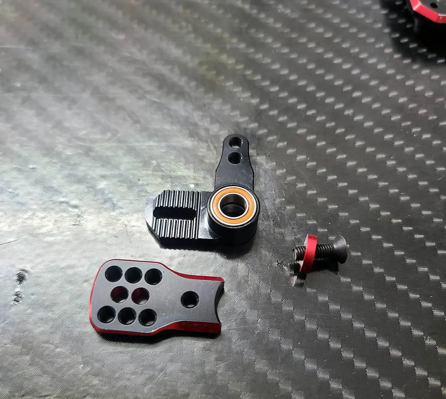
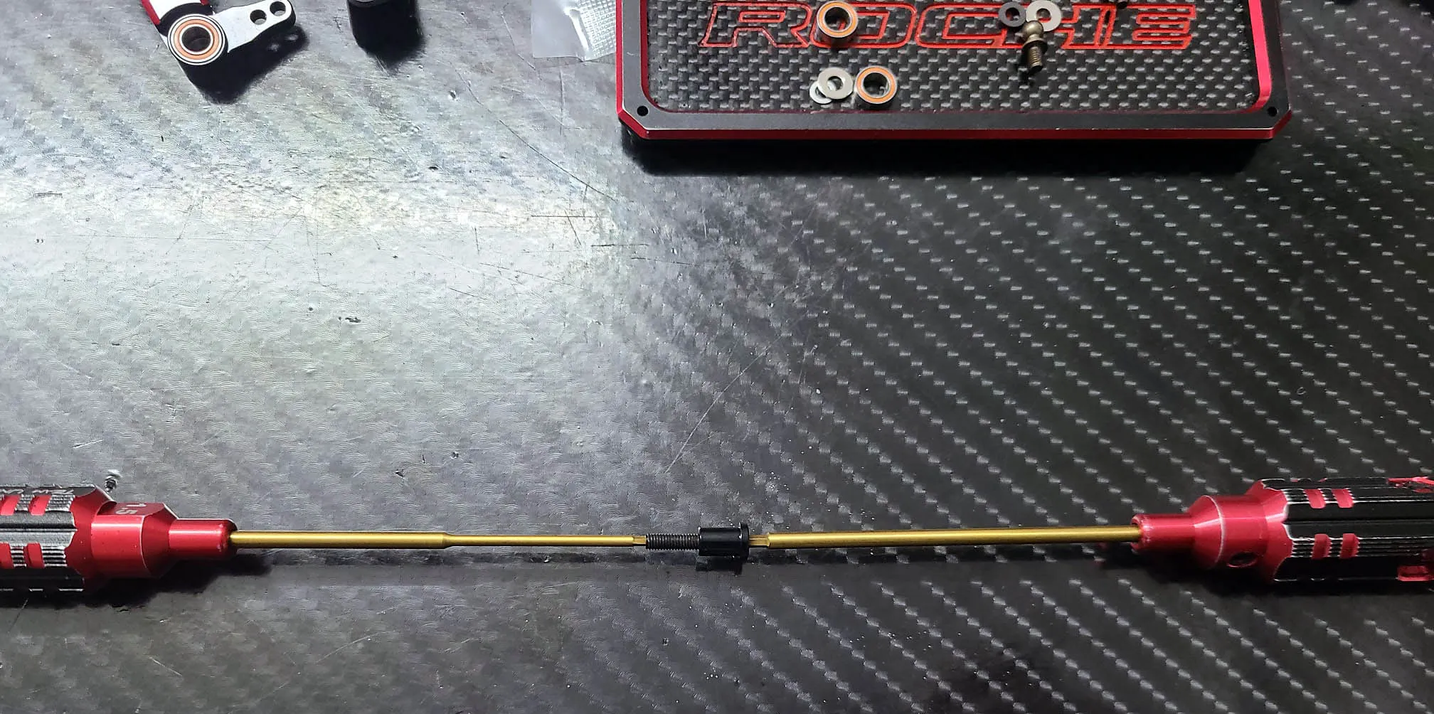
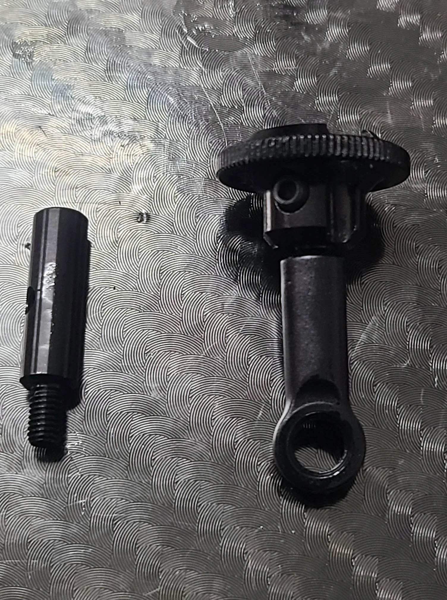
One of the most asked question will be answered here. The black post has two holes one from top and one from bottom. The bottom one is for screwing in the grub screw. The top hole is not a round hole its a hexagon. Into this hole you can insert a 2mm hex driver for easy screwing.
Take care when putting it together and don't forget the small shim under the bearings. Its important everything moves freely here
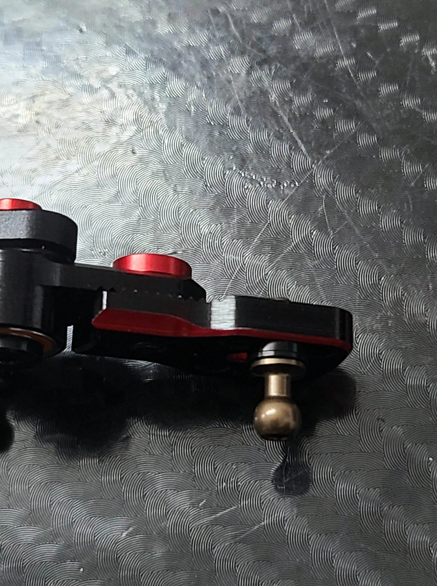
I recommand you to use a 1.5mm shim under the ballstuds to get nearly straight turnbuckles out of box. Basicly we are adjust the bumpsteer at the inside of the turnbuckle.
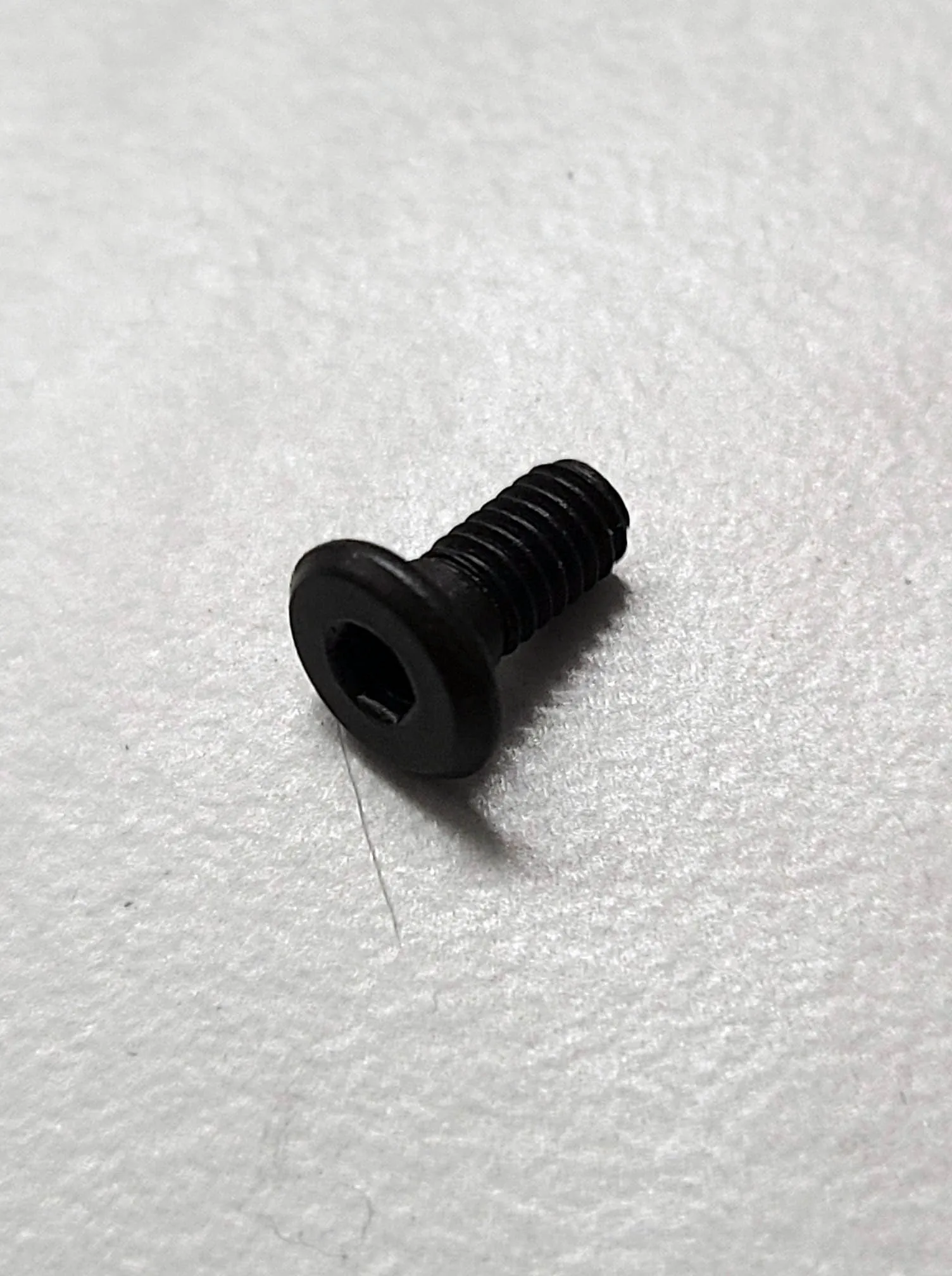
This photo shows the new ultra low profile screws introduced first time at the F1 Cars
My basic setting for the ackermann insert on the bottom of the steering arm is the backward option. If you want to adjust the ackermanm just move the top of the alloy steering more forward and retighten it.
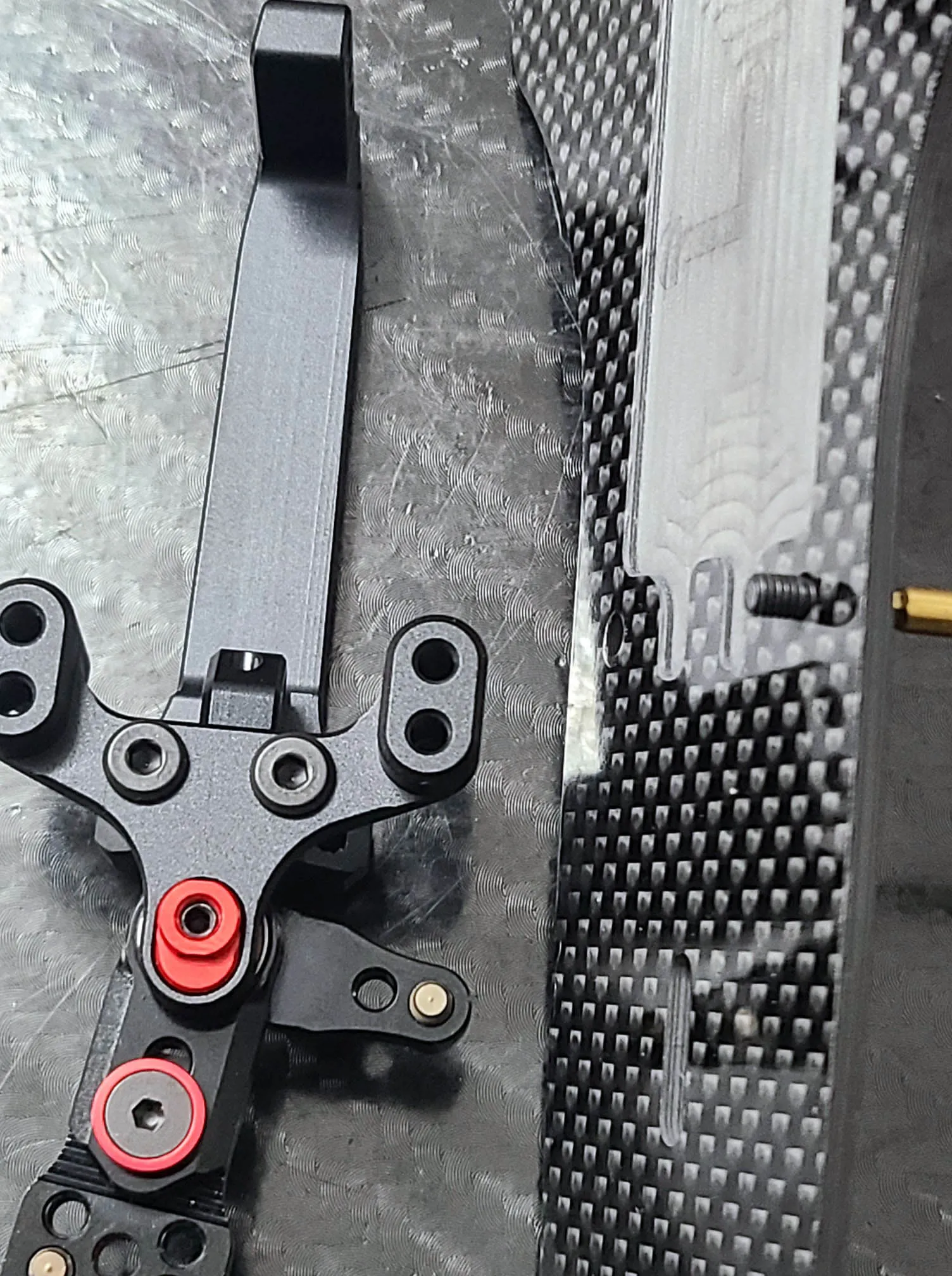
Here you can see that the countersinks are even big enough after sealing them and no screw is lower than the chassis.
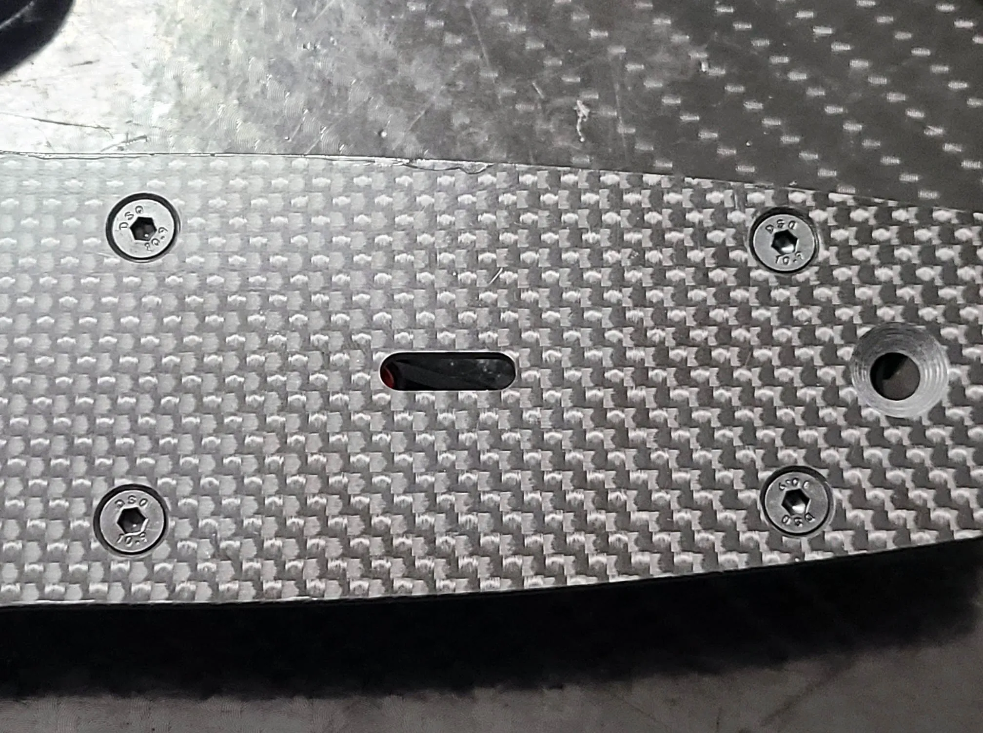
One more recommandation are the height spacer shims for the lower arms of the front. they are easy to add or remove and just make your rc life even easier. As an example I use the 0.3mm shim in this photo
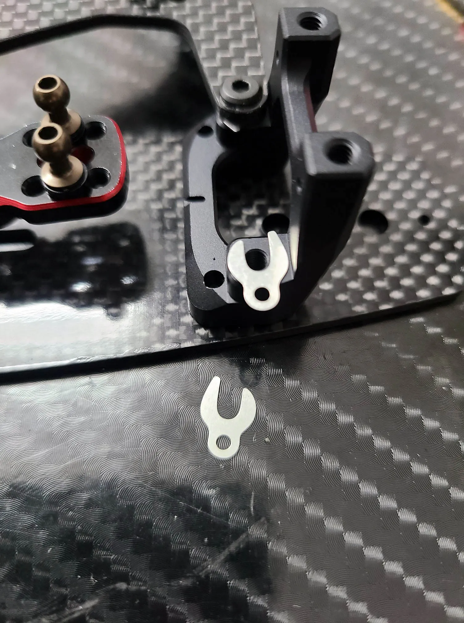
Two things can be seen here. One thing is the easy removable height spacer. just unscrew one turn and with a small screwdriver you can get the spacer removed. The other thing is the adjustable steering limiter which has two possible ways to mount. One option is for less steering angle and one for a extra portion of steering angle
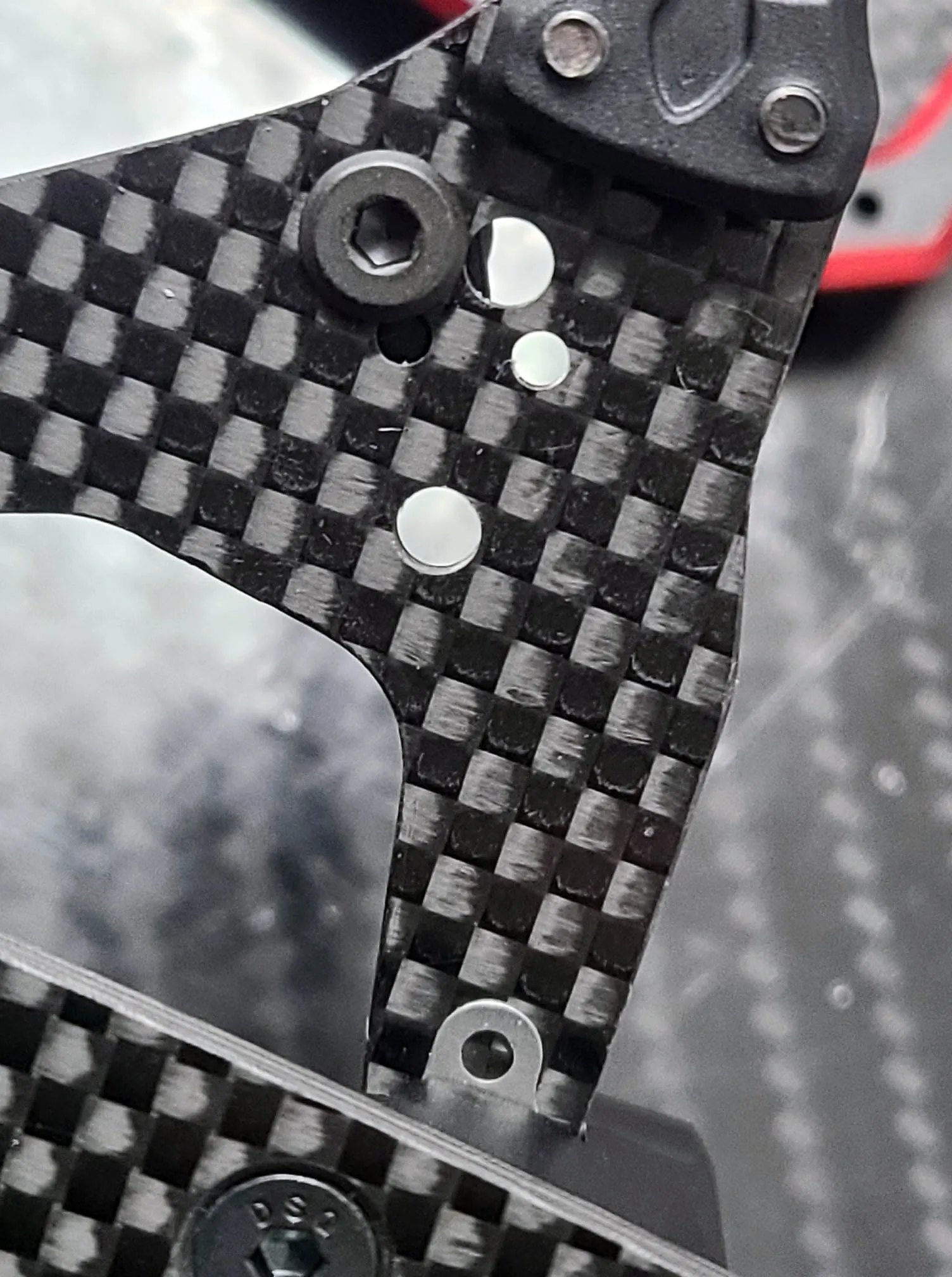
Episode 4: Turnbuckles, Kingpins, Camber and Caster inserts.
To build the turnbuckles I printed a tool with my 3d printer. The tool holds the ball cup and will make it alot easier to put the cup straight onto the turnbuckle.
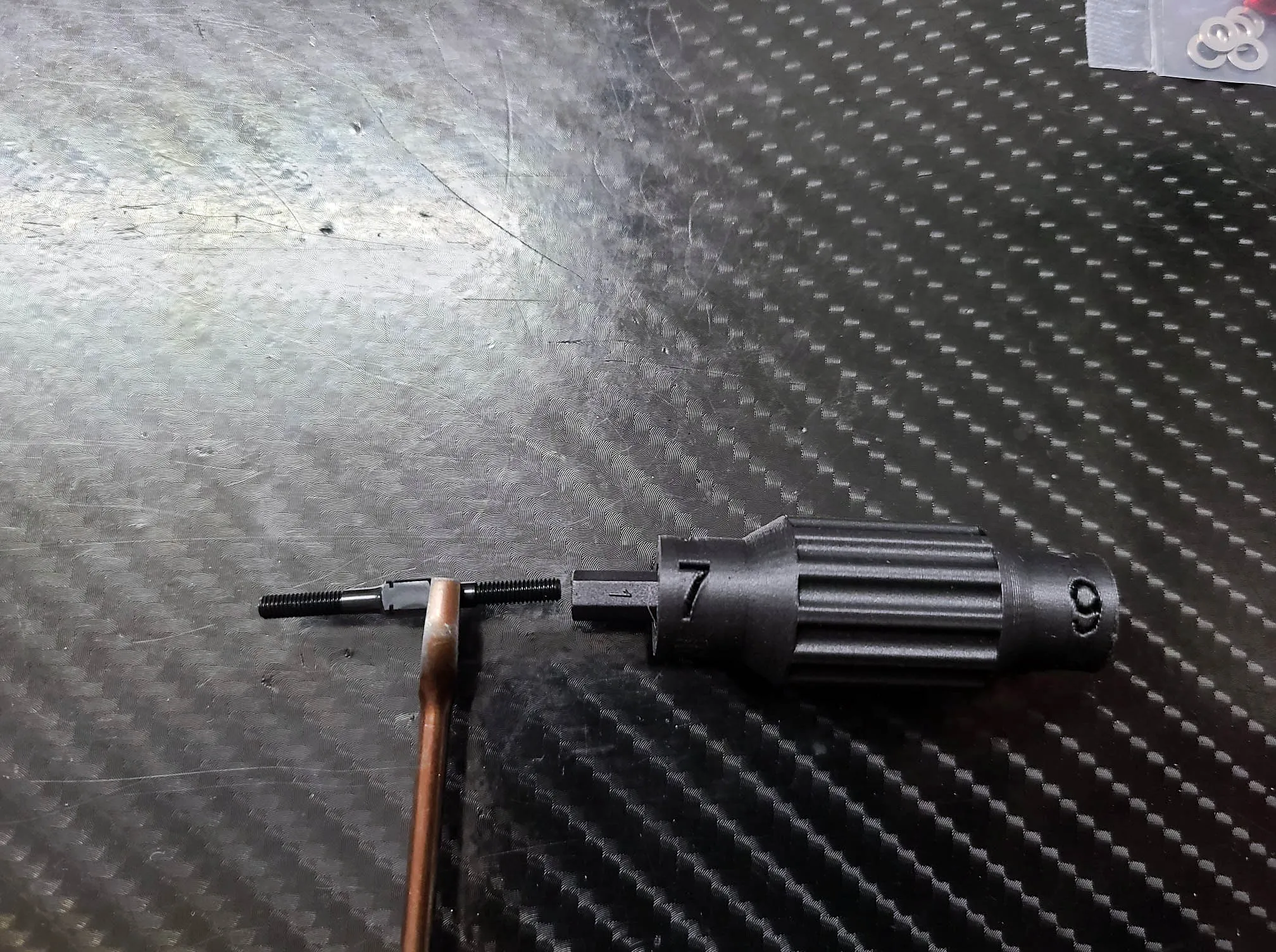
I use the measurements from the manual only as a reference. Its more important to build the front two turnbuckles in the same length and I try to make the thread of the turnbuckles looking similar on each side.
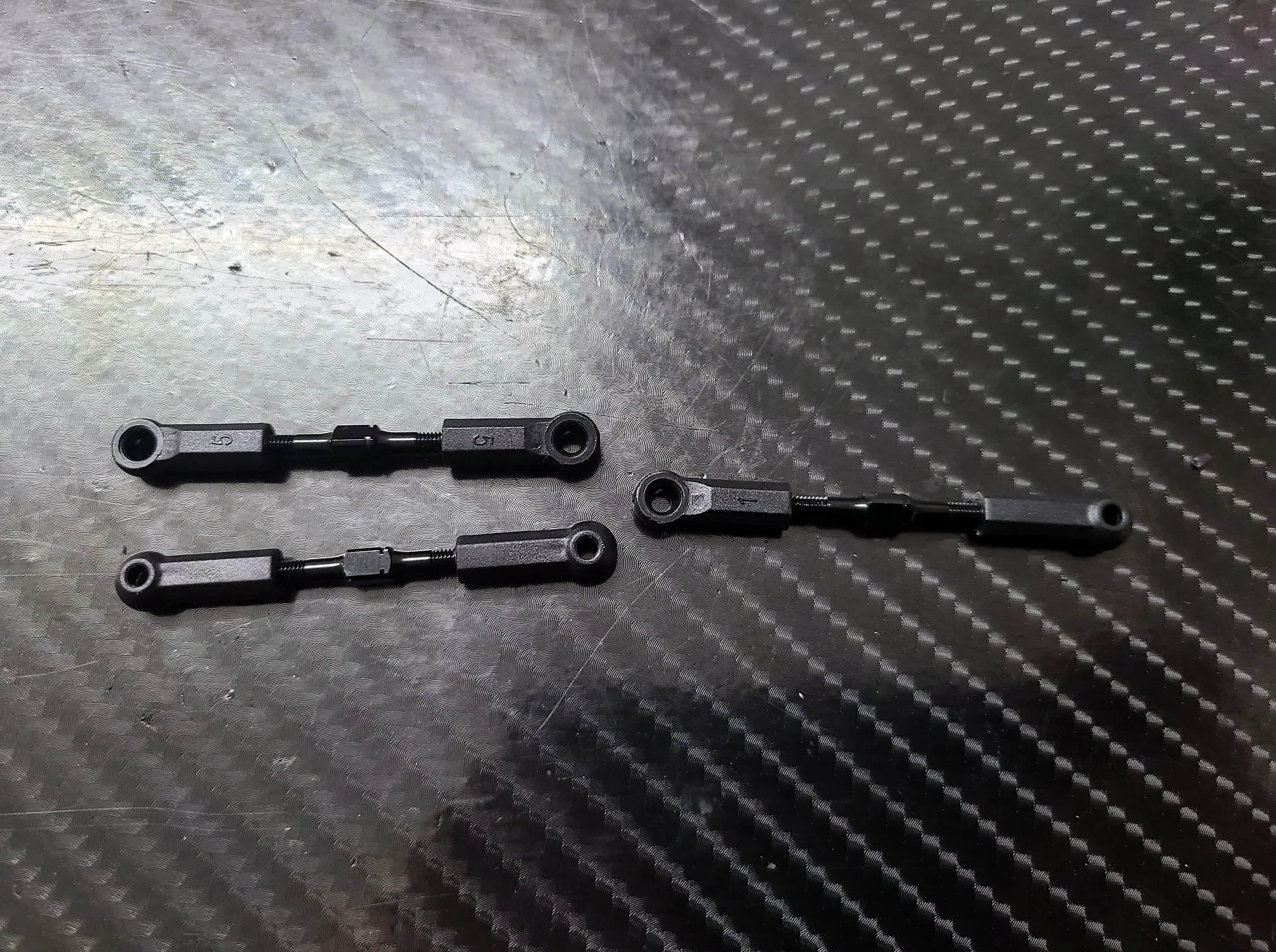
Before press the ball cup onto the steering arm take a closer look at the turnbuckles. There is a small marking which should be in the same direction for both turnbuckles
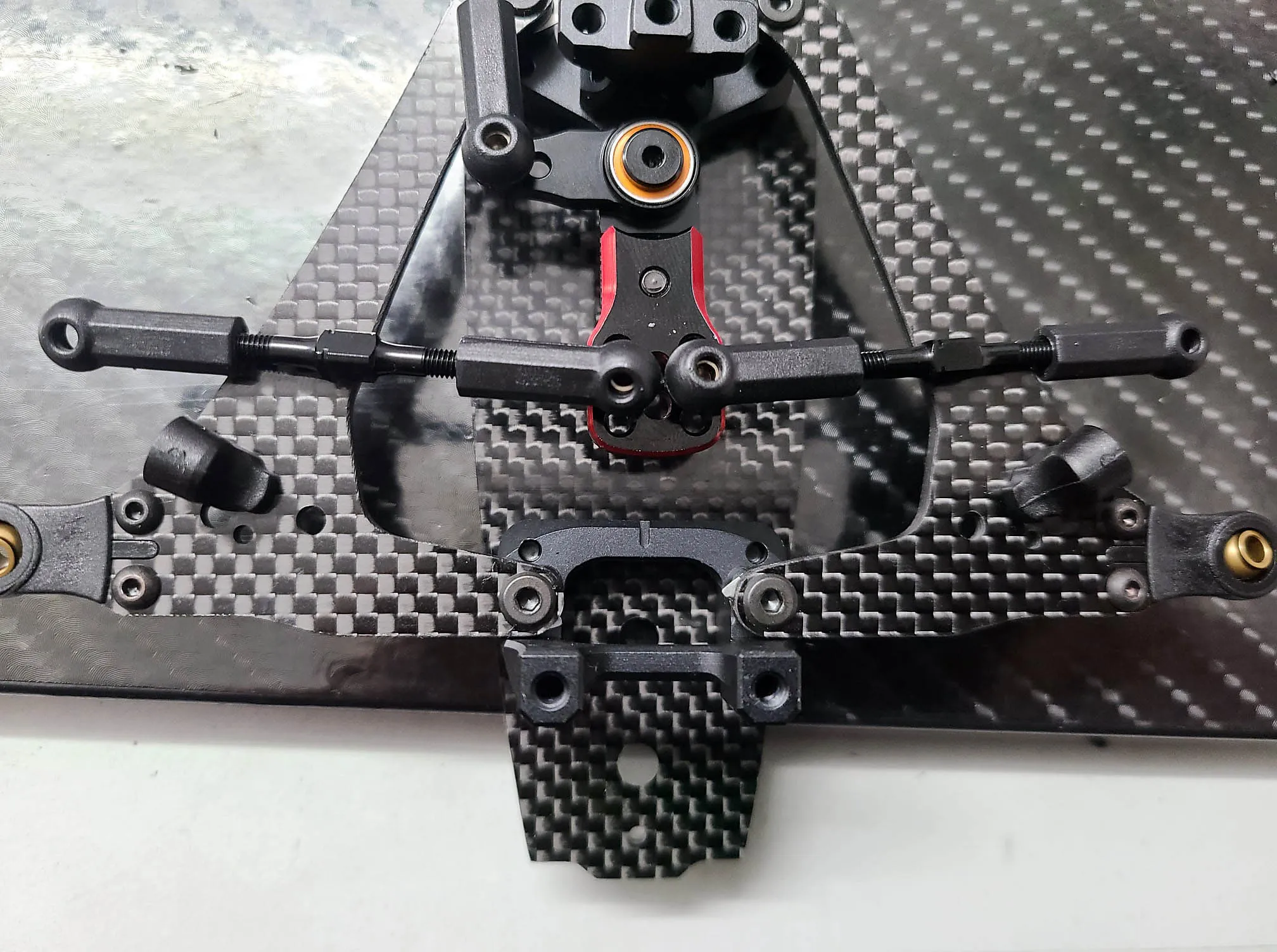
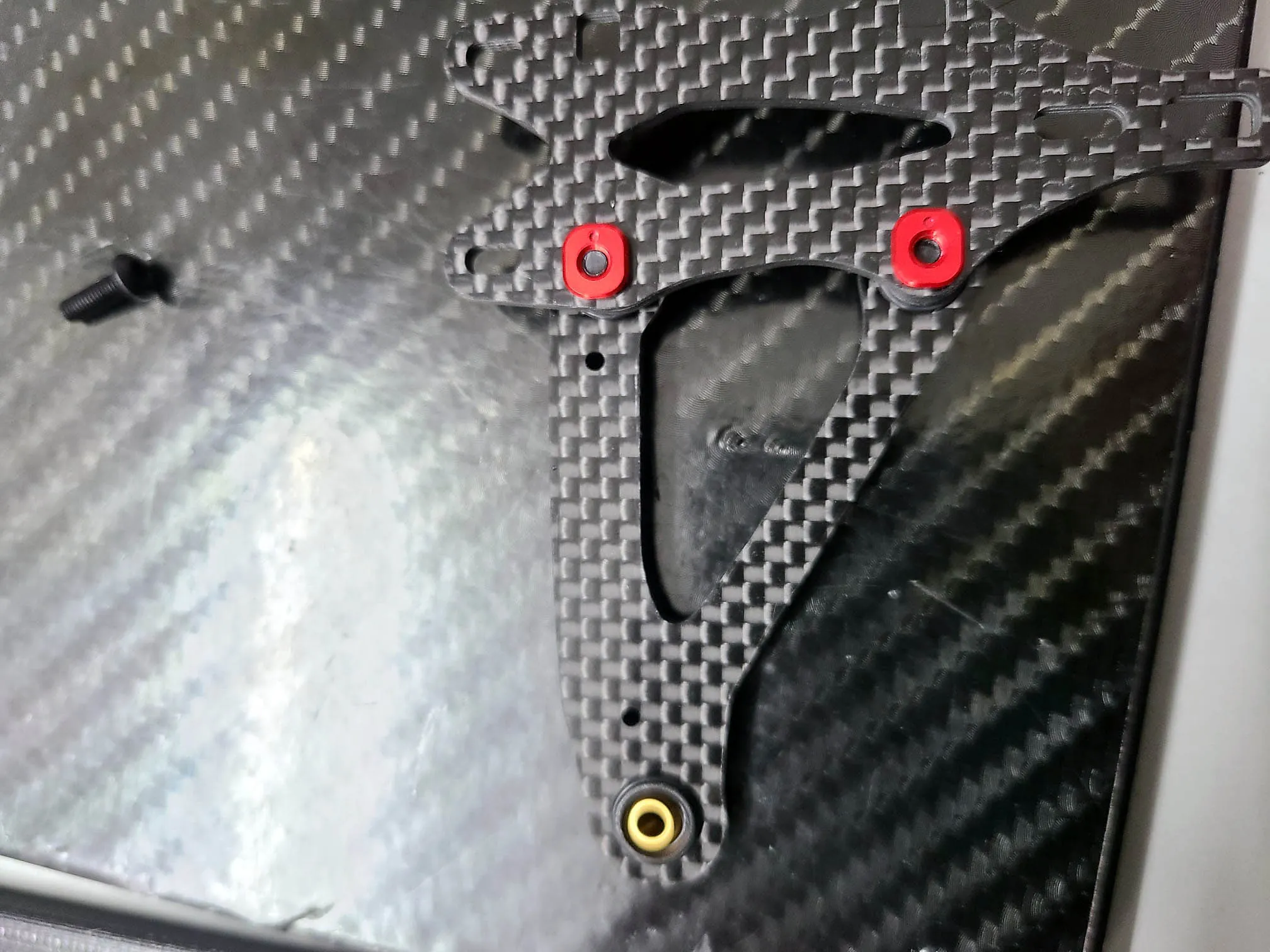
With the red inserts you can adjuste the camber of the front axle. I recommand to use 1 degree for outdoor and 2 degrees for indoor carpet racing
One of the things I use since a long time and not really easy to show in a setup sheet is the angled top arm. I always use 1.5mm under the rear of the front arm and 0.5mm at the front of the Arm. This small diffrence will be defintily noticatble while driving. Driving into long corners will be much smoother and easier to drive
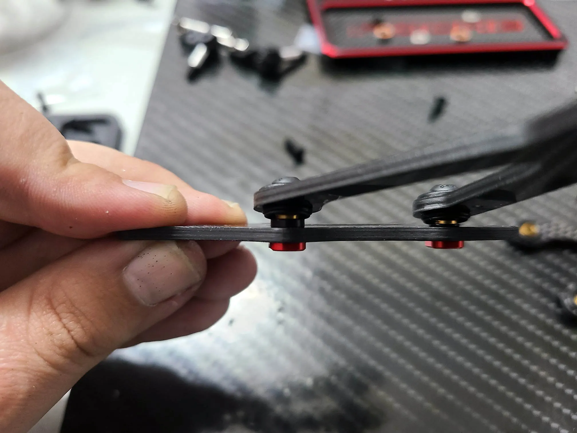
The small black insert in the back of the front arms is for adjusting the caster. I usally tent to use alot of caster angle so I mostly run 8 or 10 degree of caster.
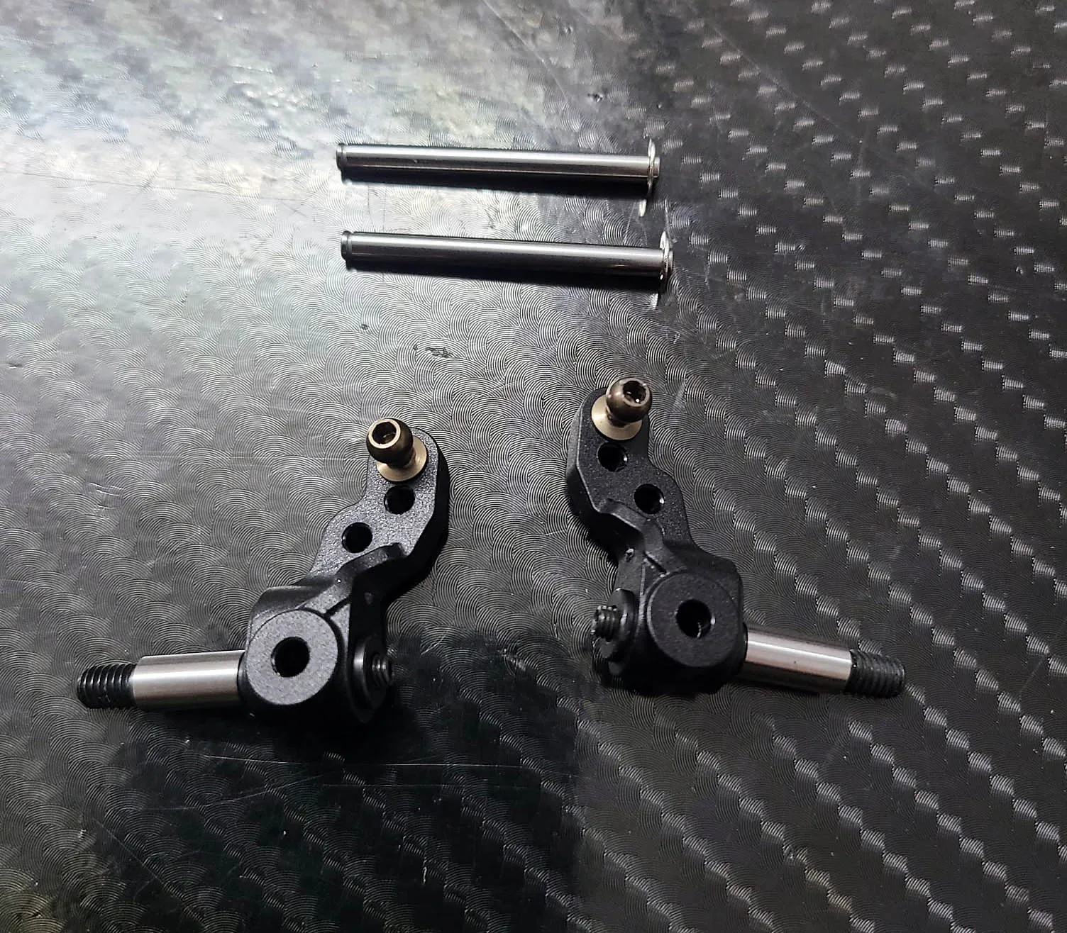
Nothing really special here but maybe incomming in future. Just as a hint this knuckle is inline and new one ...?
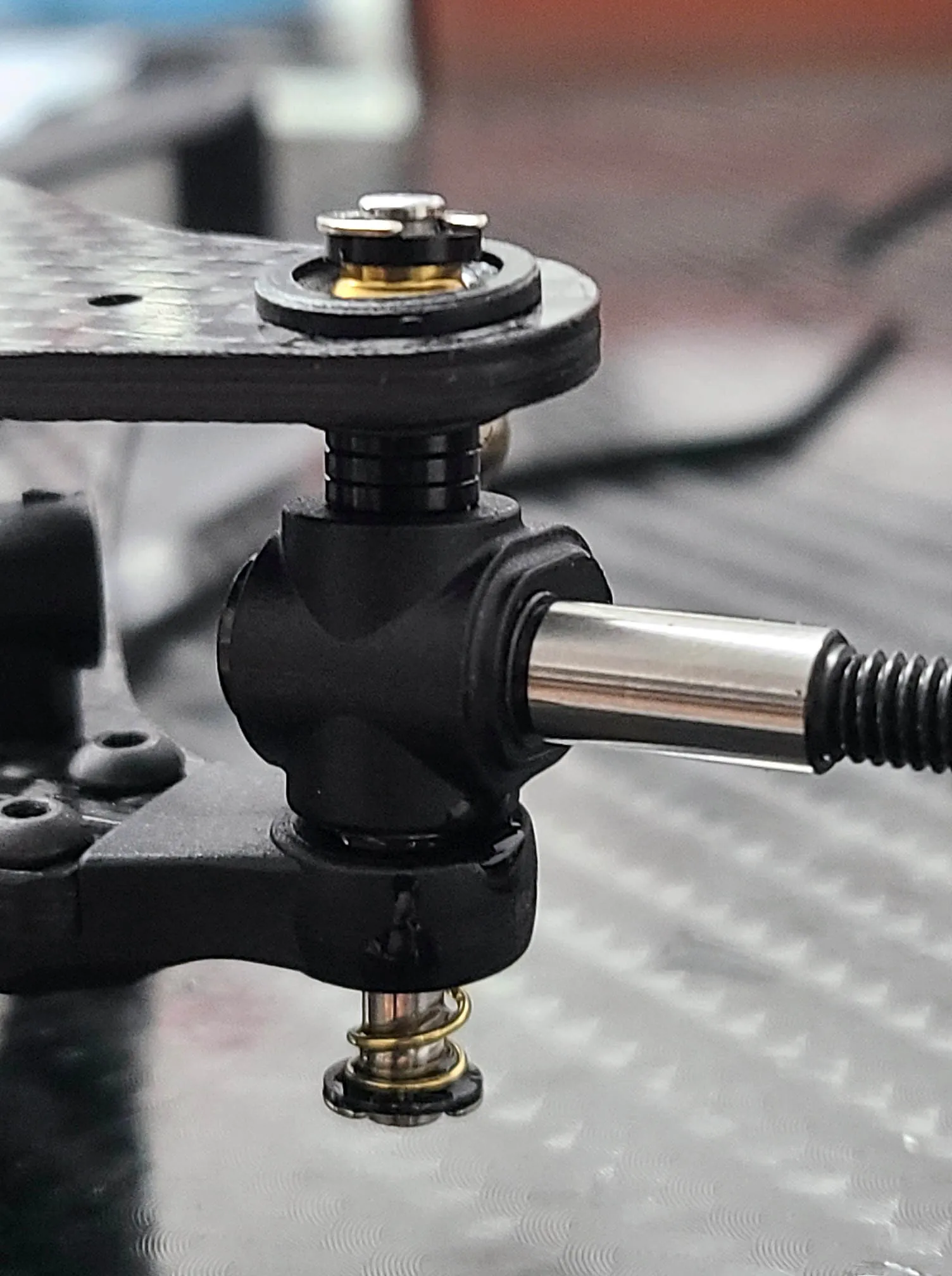
This tip just shows my preference. I don't like these silver small shims for the kingpin. I prefer good looking ones in red or black and with a diffrent height. In this picture I use black 1mm shims instead of the 0.5mm silver ones
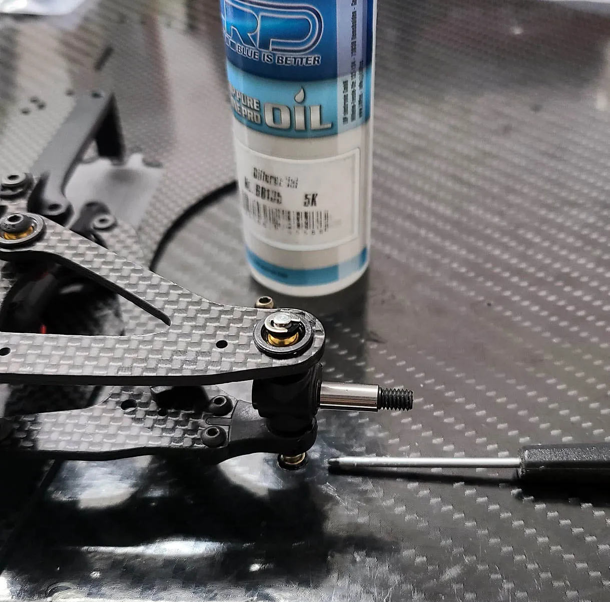
Don't forget to put some oil onto the kingpin. Feeling is defintly noticable if you use thin or thick oil there. Outdoor I recommend softer oil and indoor harder
Episode 5: Today I show you the new center pivot system, the links with its mounts and the new rear motor pod.
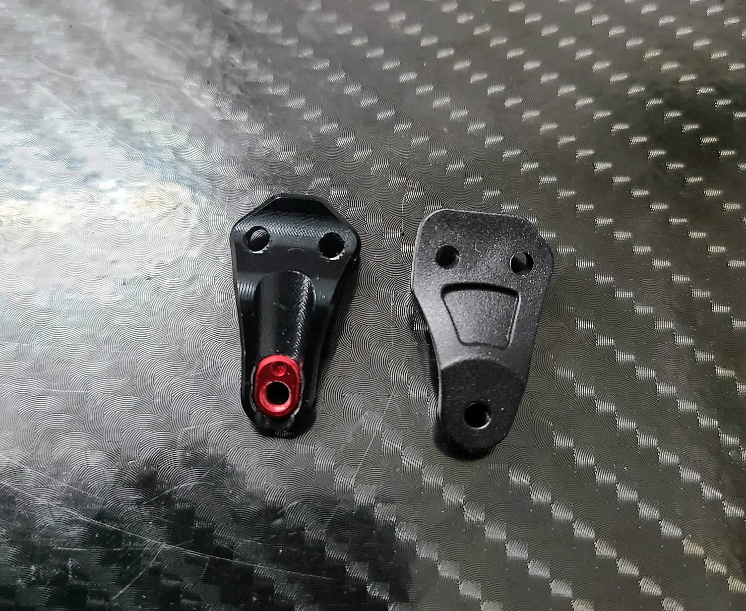
Here you can see the two possible link mounts for the Evo 3. The right one is made by plastic and included in the kit. The left one is the optional adjustable mount made by alloy. In my opinion the alloy mount is a very usefull option for tuning the setup. Basicly you adjust the angle of the links which lead to a diffrent feeling at turn in.
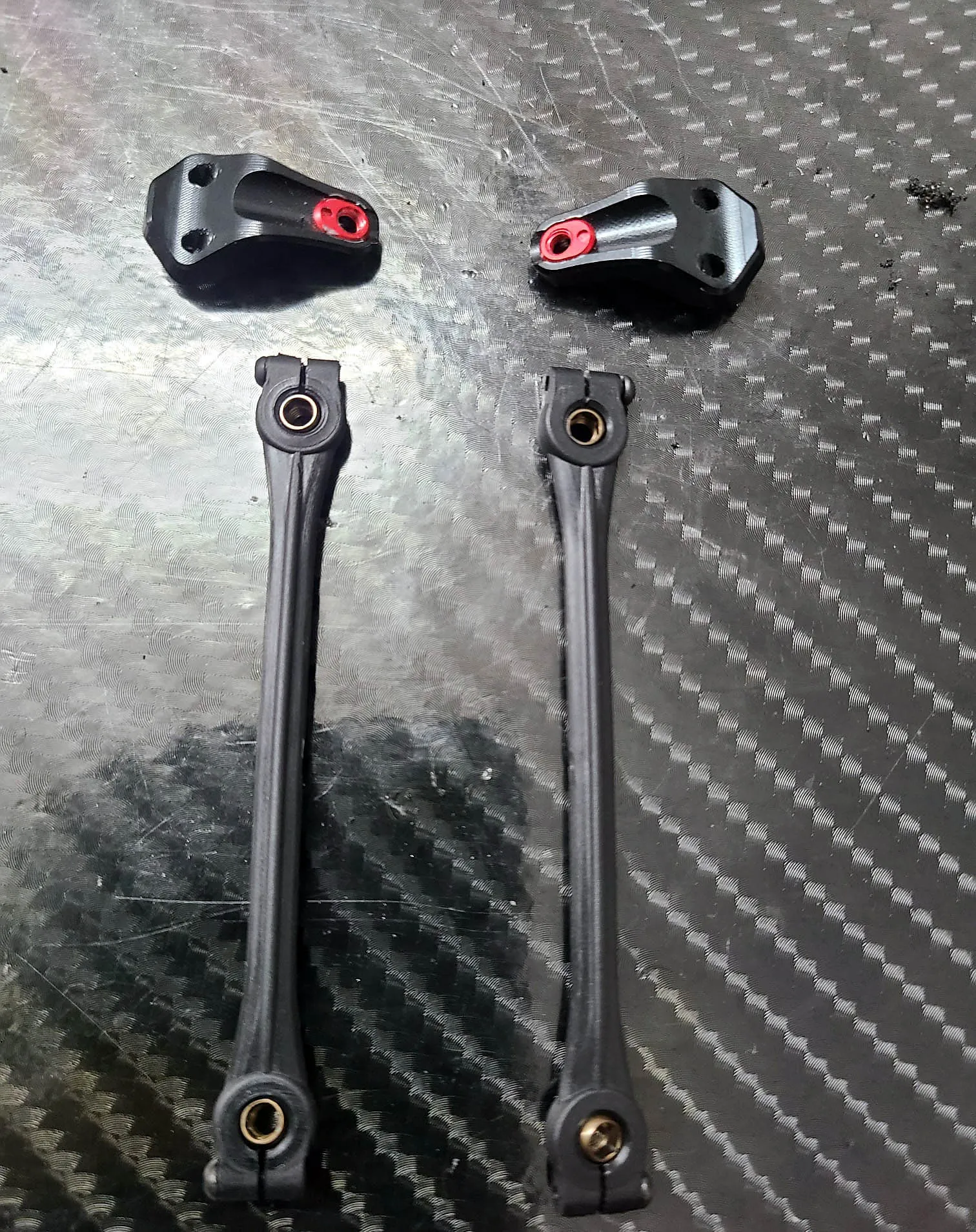
For asphalt racing I recommand to put the inserts for the link angle pointing to the outside. It gives you an easy to drive car and a straight link. By the way take care about the direction of the balls in the links and don't put them in like me 😃
The link mounts are connected to chassis with two screws to prevent any tweak or misalignment of the rear pod.
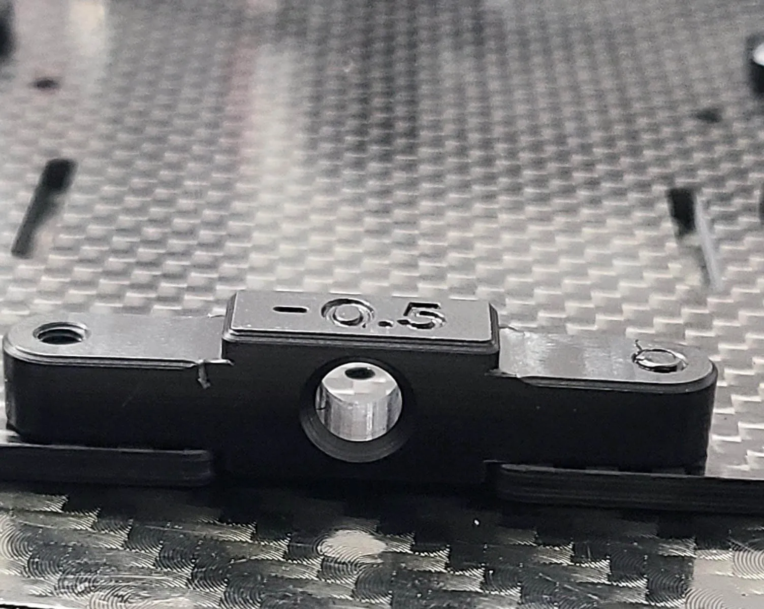
Everyone who uses the F1 Evo2 will know this part and it still does the job well on the Evo3 but due the new center pivot mount on the rear pod another setup option is introduced. We can finally add shims to put the pivot in a higher postion. With this new higher pivot we can easily increase the rear rollcenter and this is definitly a gamechanger for carpet racing. In case you add shims add them on chassis side and on rear pod side otherwise you will have an angled rear pod.
Lowering the pivot is still possible like on the Evo2 with flipping the mount.
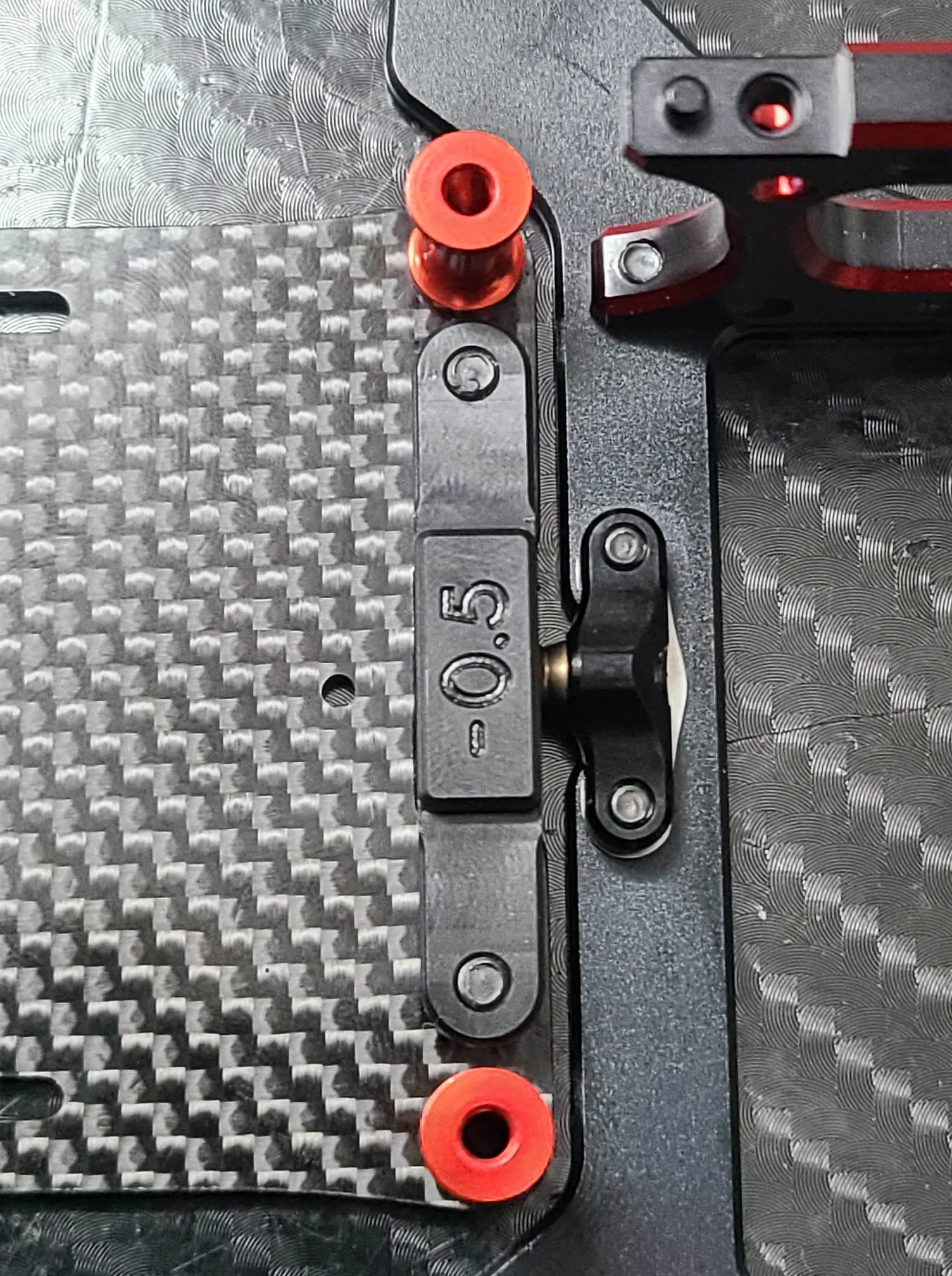
While building I decided to start with the 0 mm pivot offset variante which gives you more on power steering. The choosen offset can be read from the bottom of the chassis.
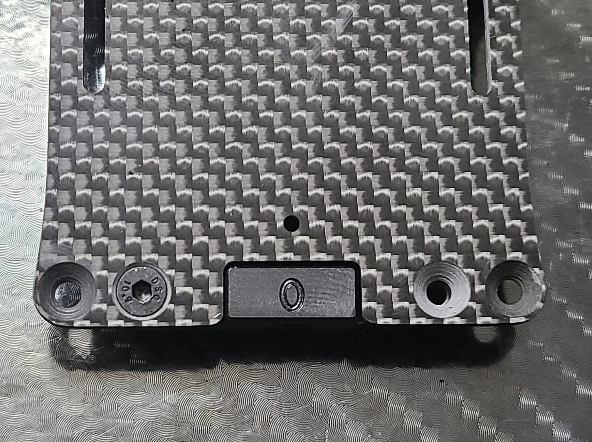
In this photo you can see the already mentioned new center pivot mount with the needed shim according to the manual and the new alloy rear pod.
One of the most asked question till now is why the Evo3 has an alloy rear pod and not a graphite one. There are two reasons for it. On the one hand the motor can be lowered by 0.5mm and on the other hand it removes flex from the rear of the car and increases the weight at the lowest possible place of the car.
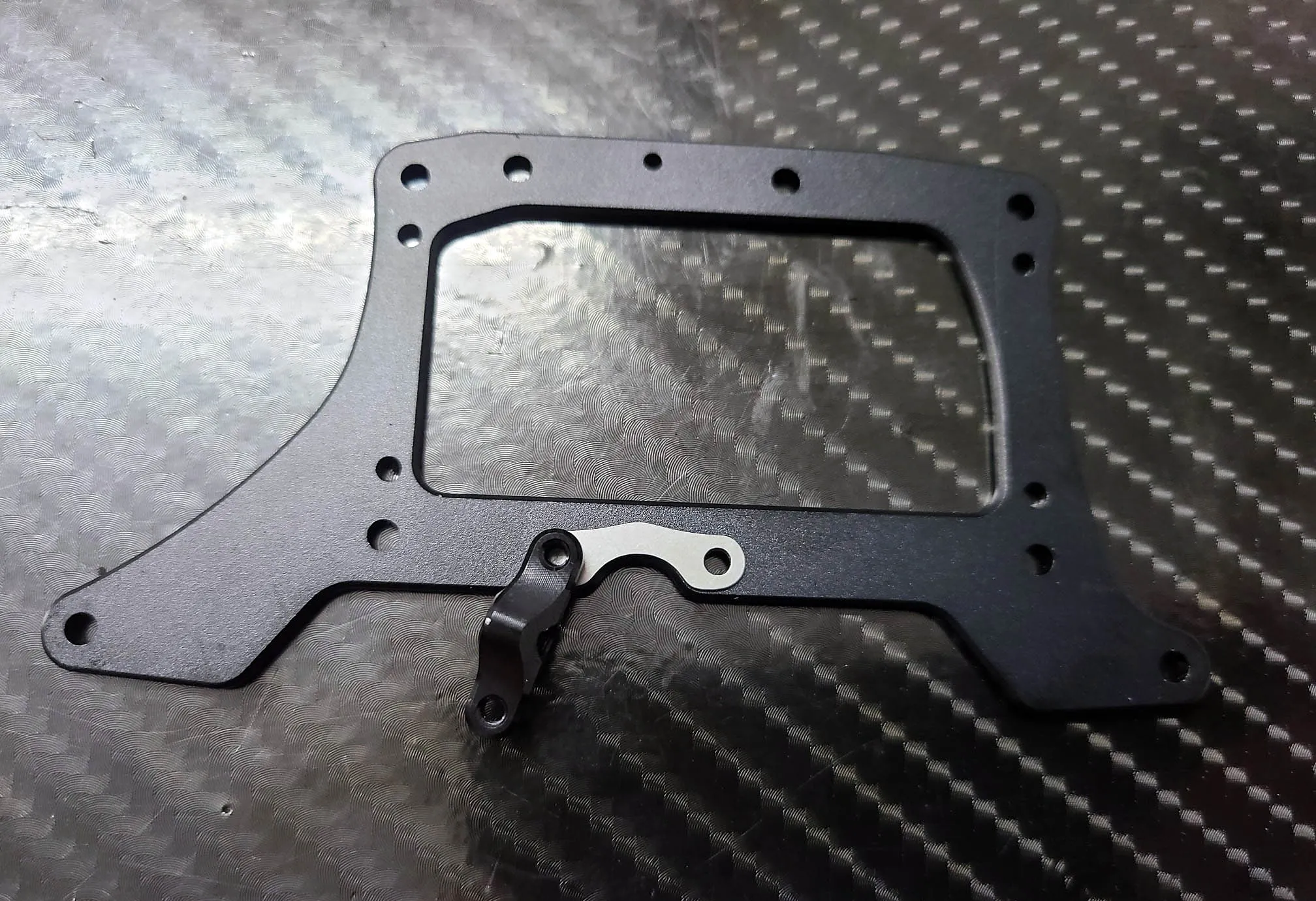
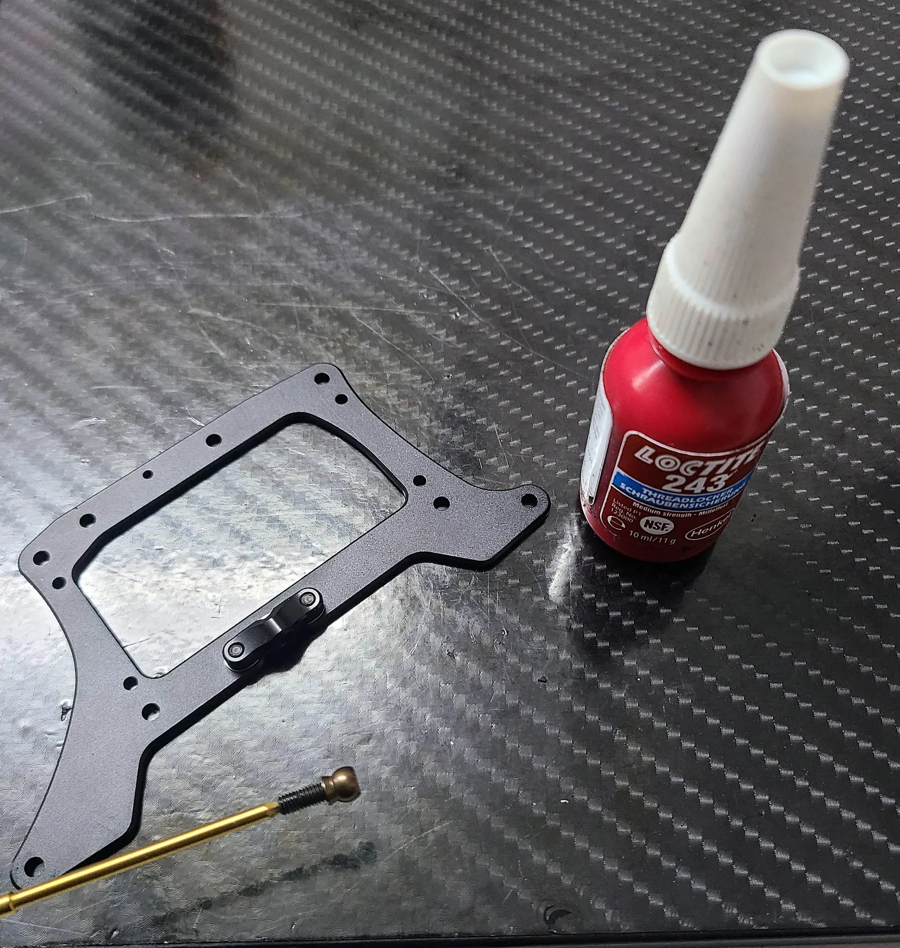
This is one thing I recommand for everyone just put a small amount of loctite at the grubs screw from the pivot ball when screwing it to the center pivot mount.
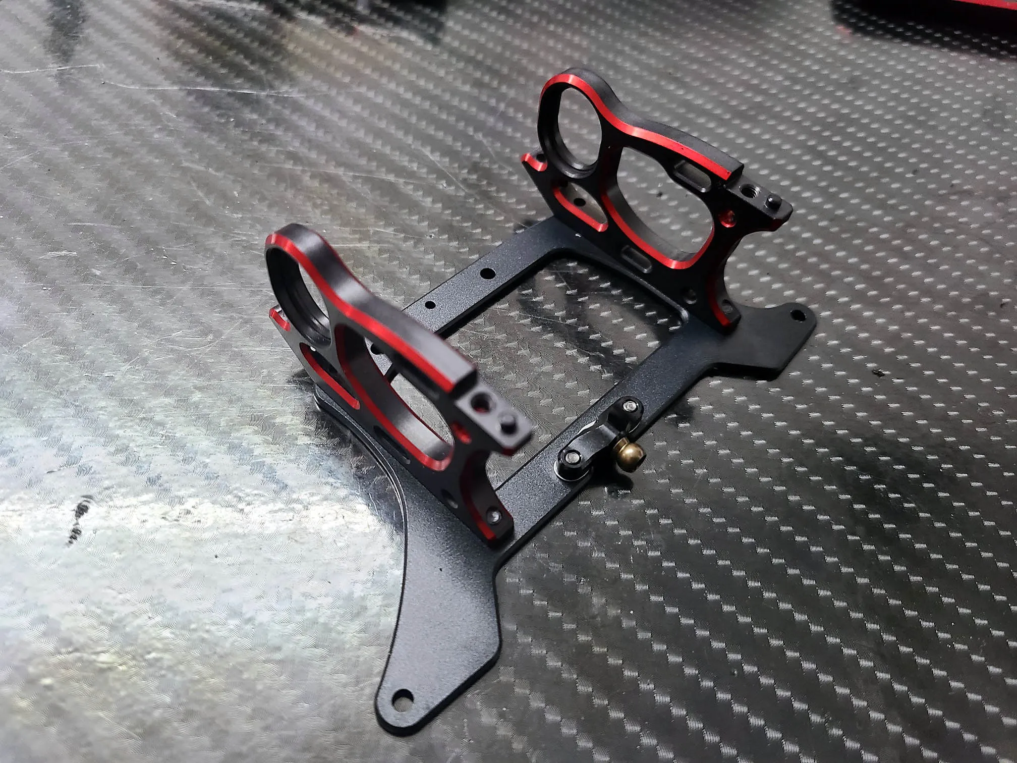
The new motor mounts still have the nice black and red coating but the way to adjust the height of the car has changed. Now the Evo 3 follows the 12th Scale cars from Roche and uses different height adapters.
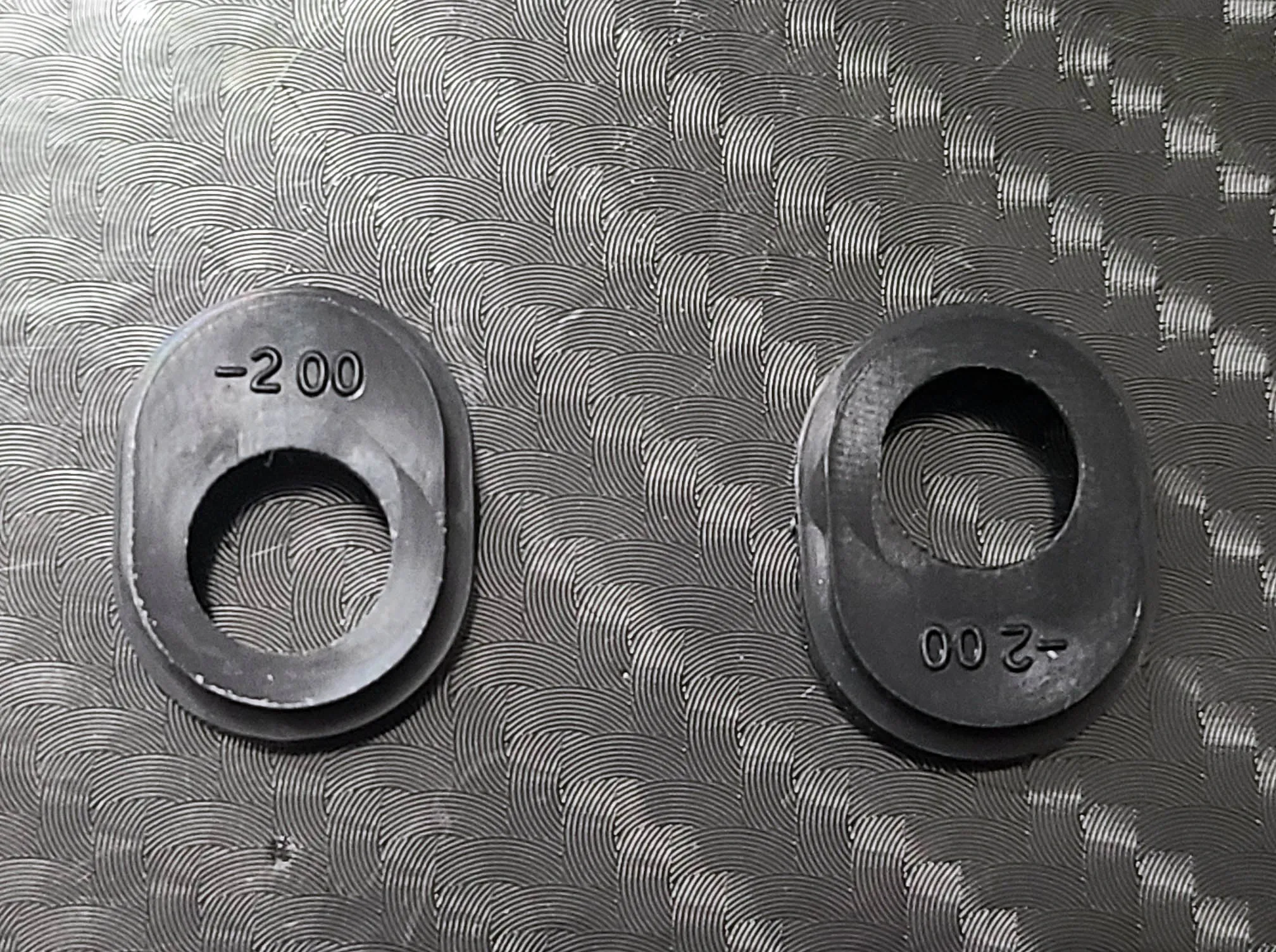
For the Evo3 Roche has made alot of different offsets. Starting from 0 to 2mm we have every possible option in 0.25mm steps. With this parts you can adjust the height of the rear axle very precise
The rear pod is only connected with the links and the center pivot to chassis. Its very important that evrything moves freely and cause no binding at all. In case you have some binding or to much play adjust it with the small screws around the balls of the links.
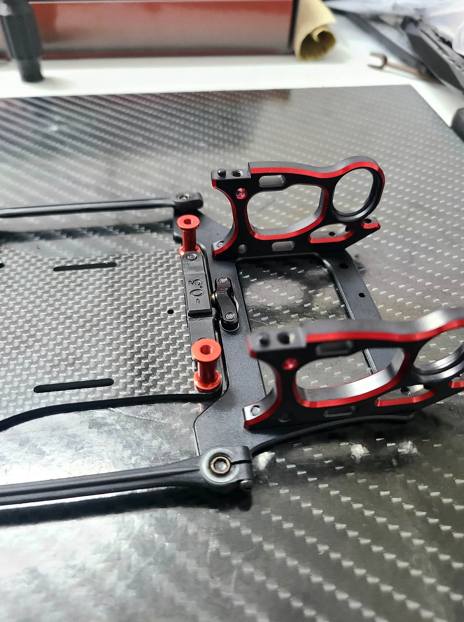
This is one of the most important pictures for everyone who is using the F1 Evo 2 or the new F1 Evo 3. Its super important that the gap between the rear pod and the chassis is the same over the complete lenght. Otherwise you will have tweak in your car which can lead to an unpredictable car. If your gap is not the same over the complete length uscrew the link mounts and try to align the gap with postion of the link mounts.
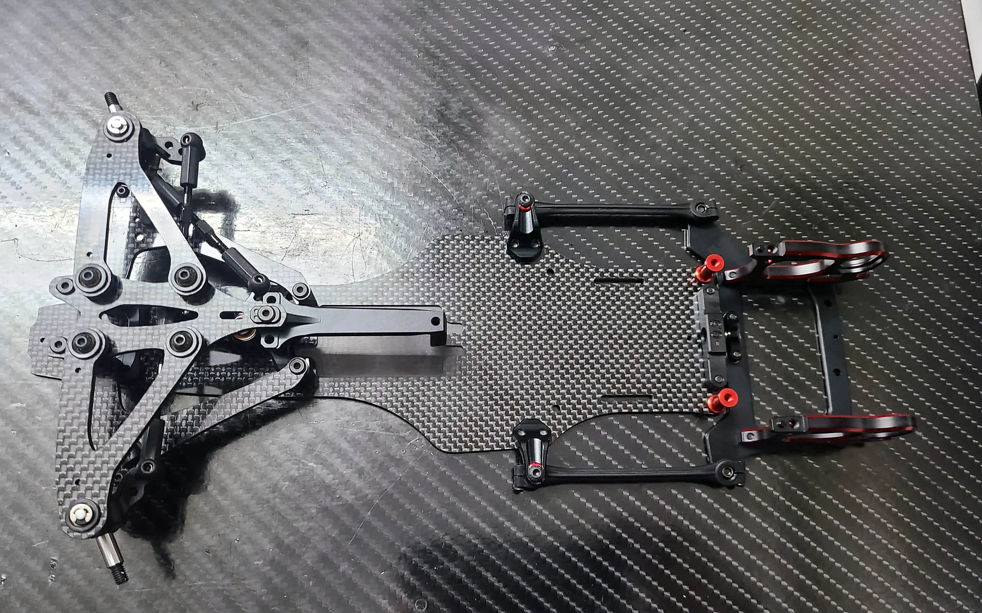
Its finally looking like a car
Episode 6: Just a few new things but some tips from my side while building.
I will show you the build process from the wing to chassis mount inclusive the mounting of the side-springs and the side-tubes.
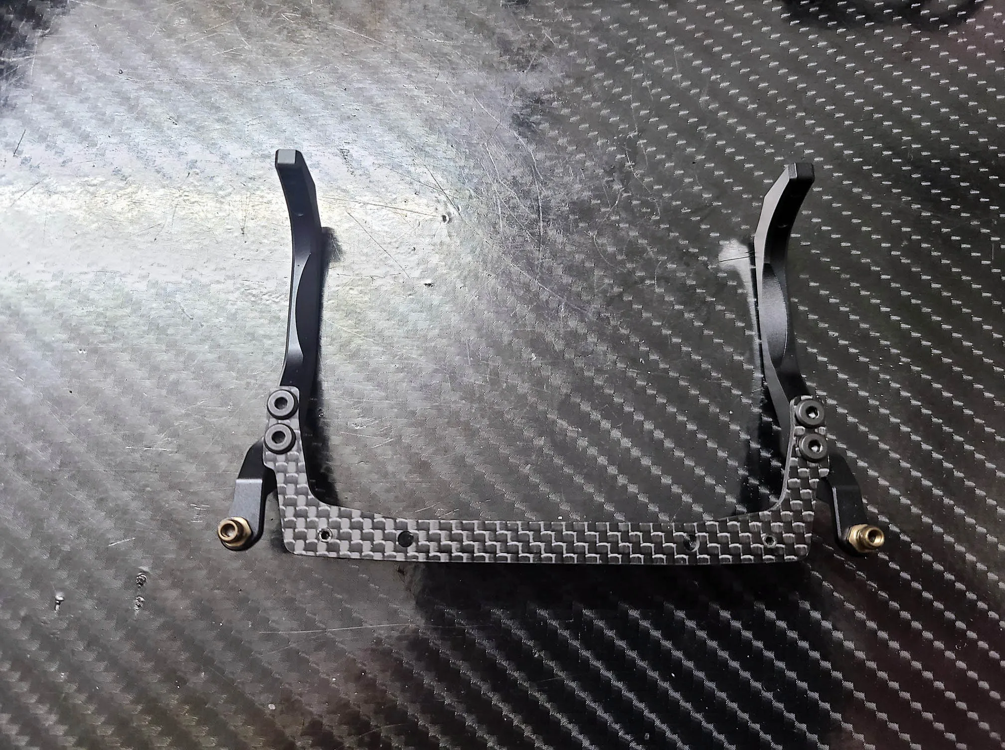
These 3 Parts are the main things you need for the wing to chassis mount. The alloy parts for each side and the center plate made by carbon are the same as the ones from the Evo 2.
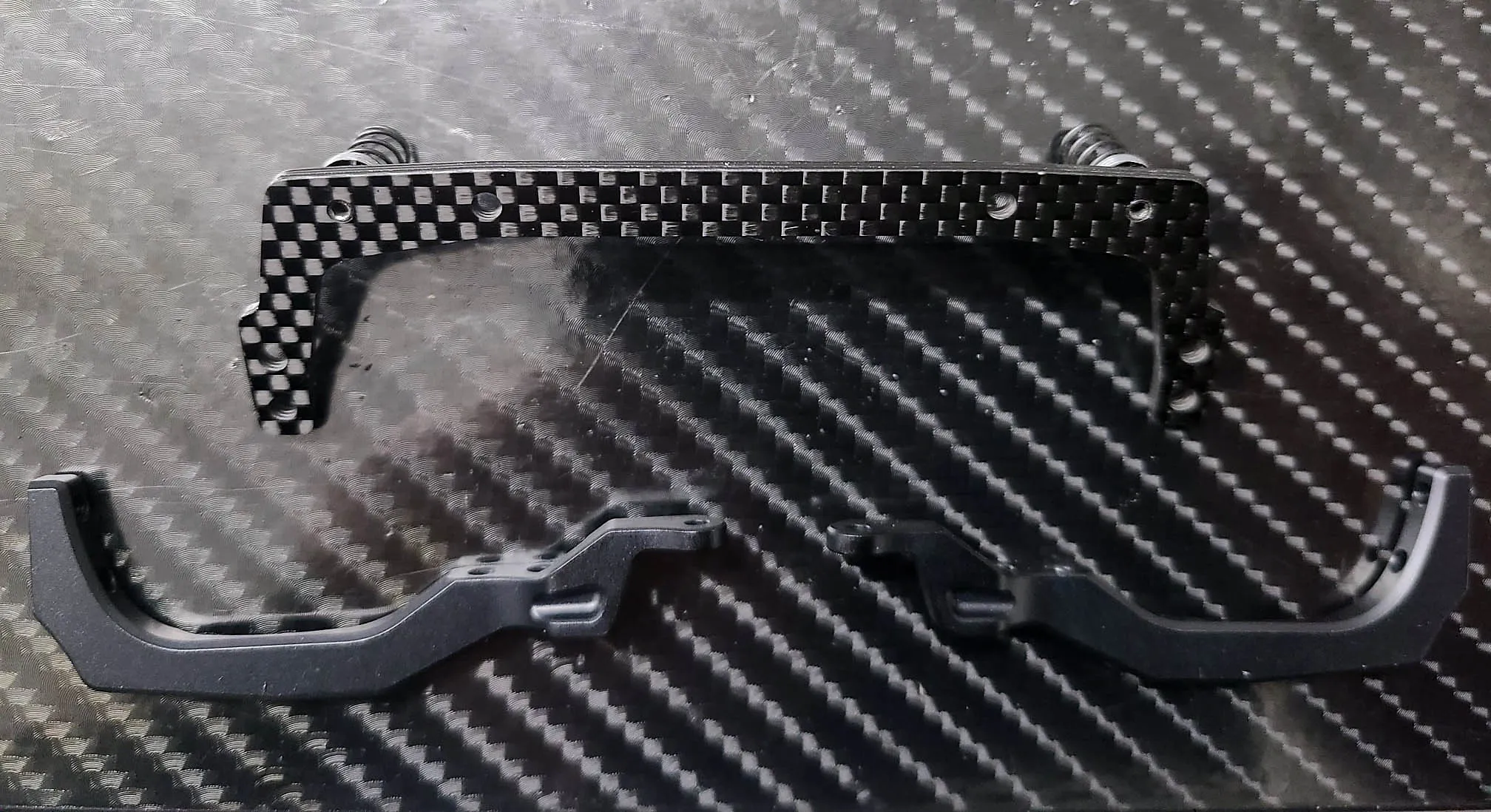
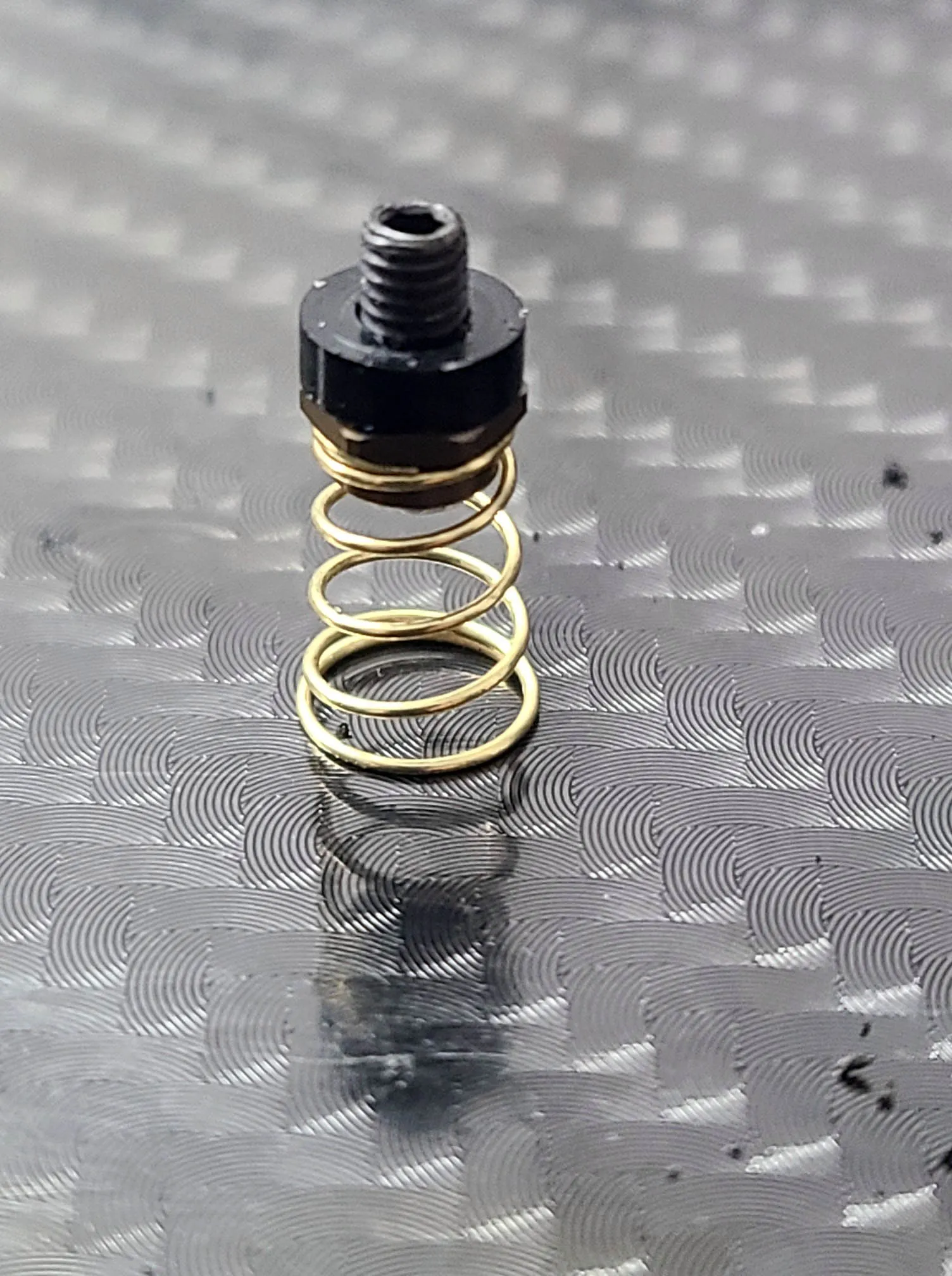
Here you can see the new Sidespring holders. The colour has changed from red to gun metal but the spring is fitting alot better than before. Just as small tip from my side I always put a 1.5mm shim on top of the spring holder to get a good starting point when you retweak your car. With this shim the tension is same on each side.
Put all mentioned parts together and add the balls studs for the Tubes yours should looks similar to this photo.
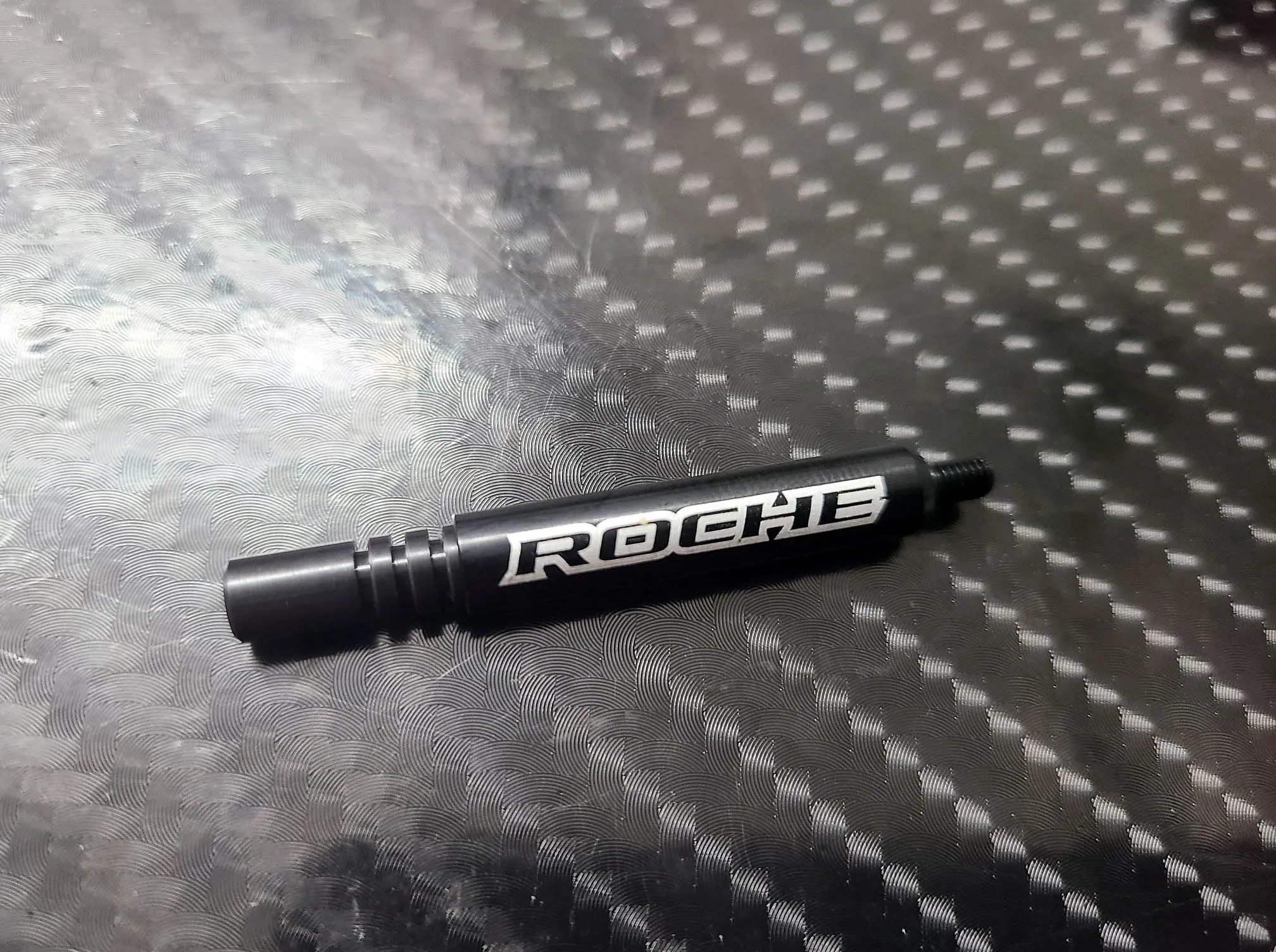
First of all I was very disappointed. My plastic cylinders are missing for building the tubes. I searched in every package but nothing there. In the end I was just blind. The cylinders are inside the tube already 😃
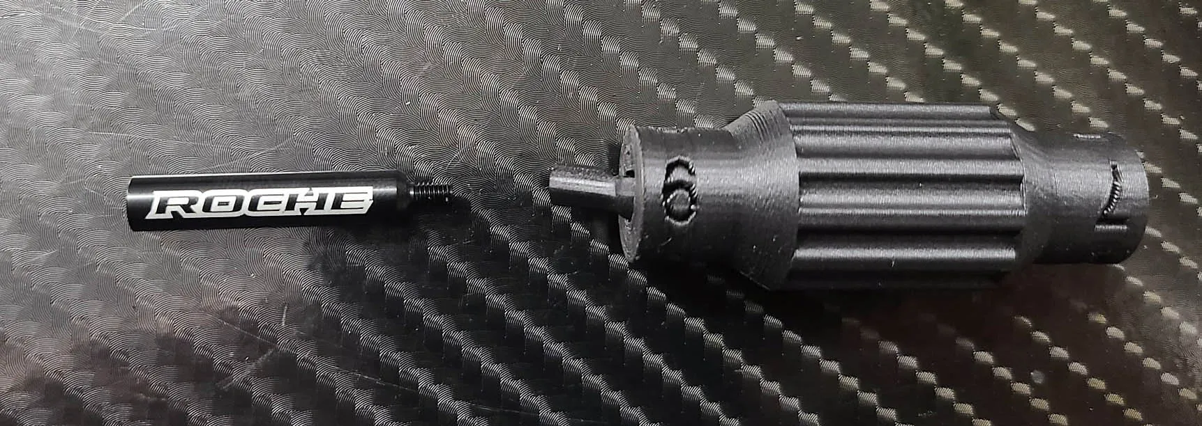
To put the Ball cup onto the Tube I use my selfmade ballcup tool again. If some one is interessted I can send you the file and you can print it for yourself
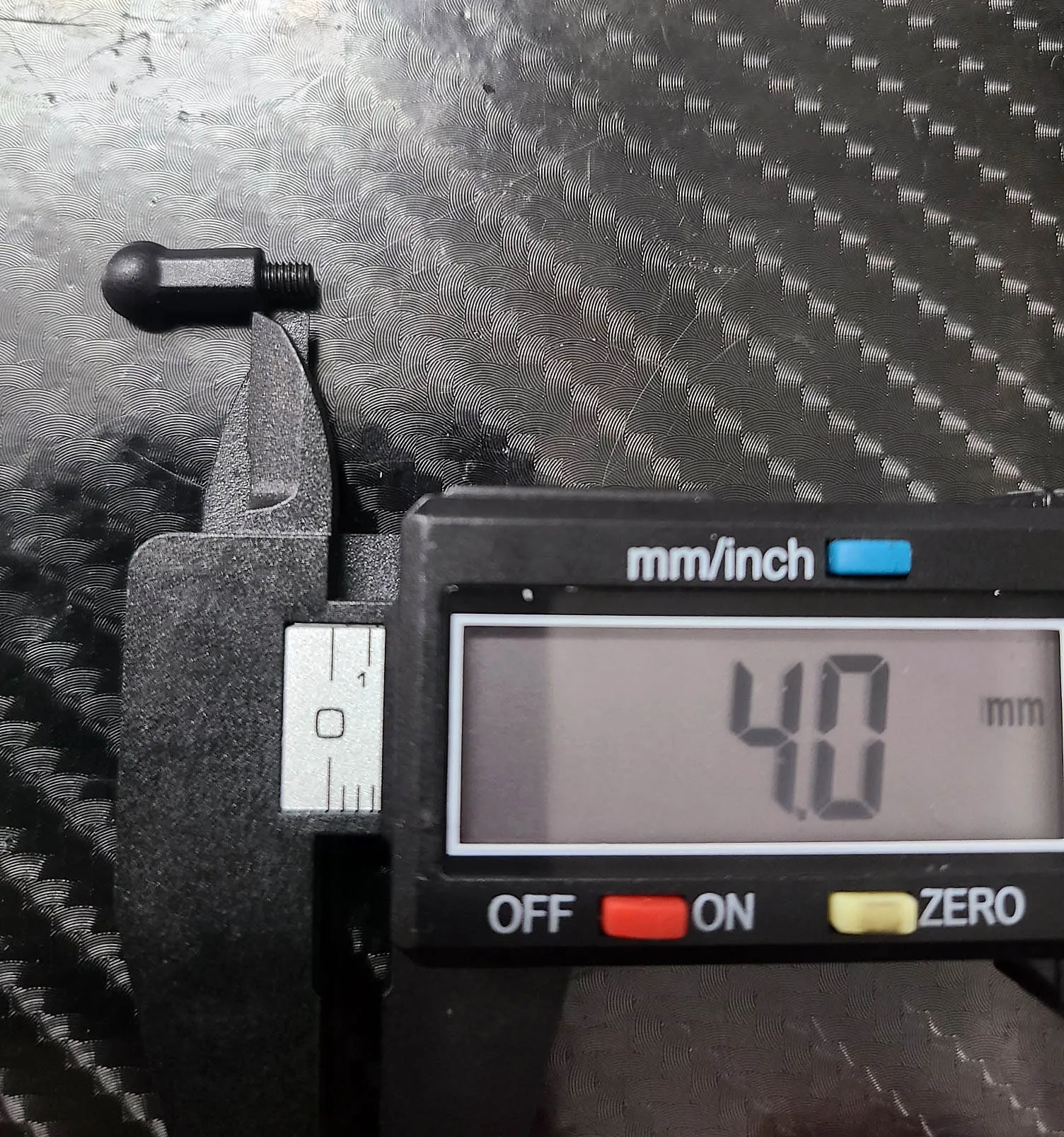
Something which is not mentioned in the manual is how much milimeters the grub screw should be screwed in. 4mm Thread out of the ball cup worked fine for me always.
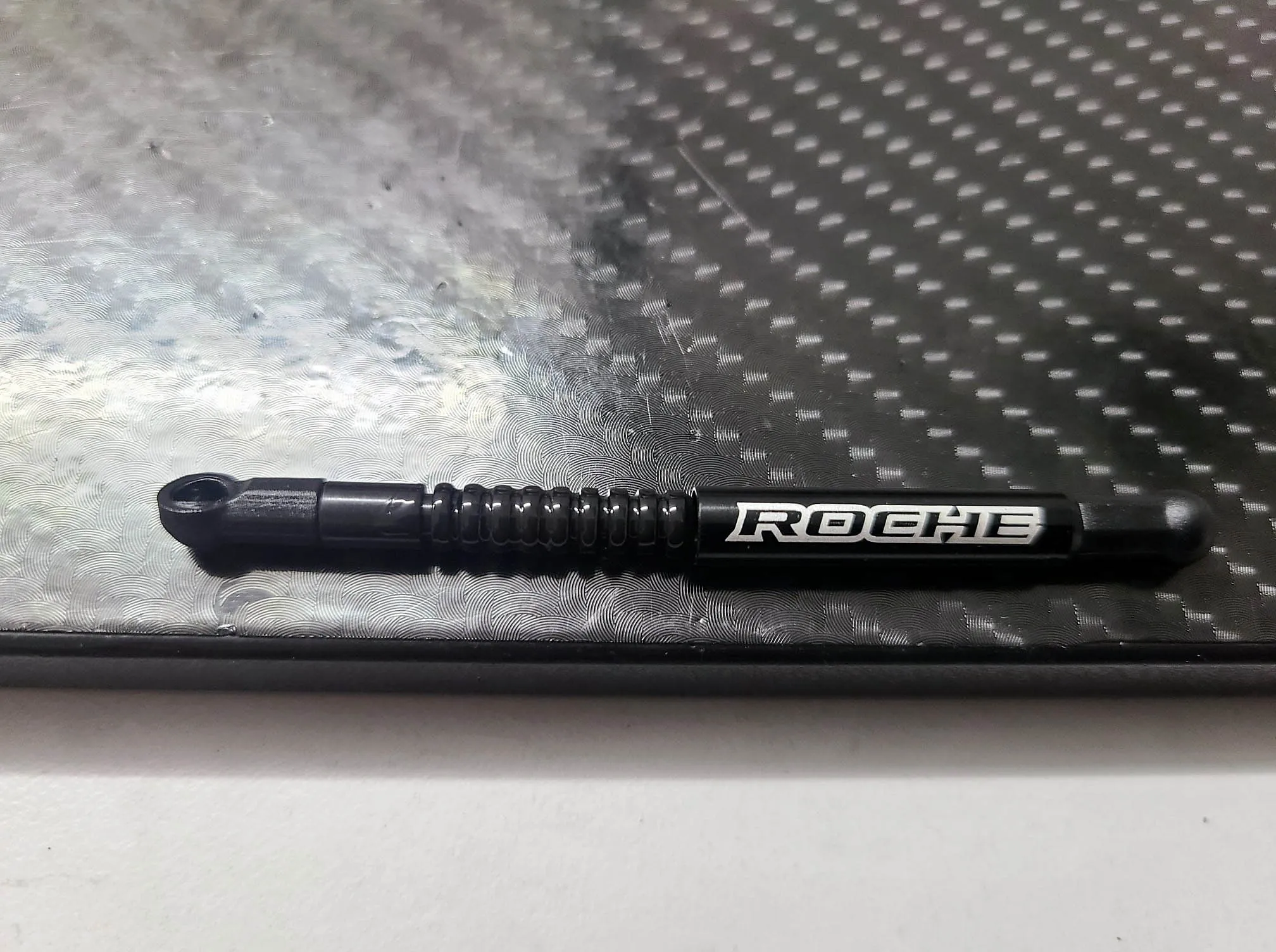
The complete Sidetubes is finish after adding the cups and just a bit of oil should be added to the slots of the cylinders. Inital I recommand 30.000 cst.
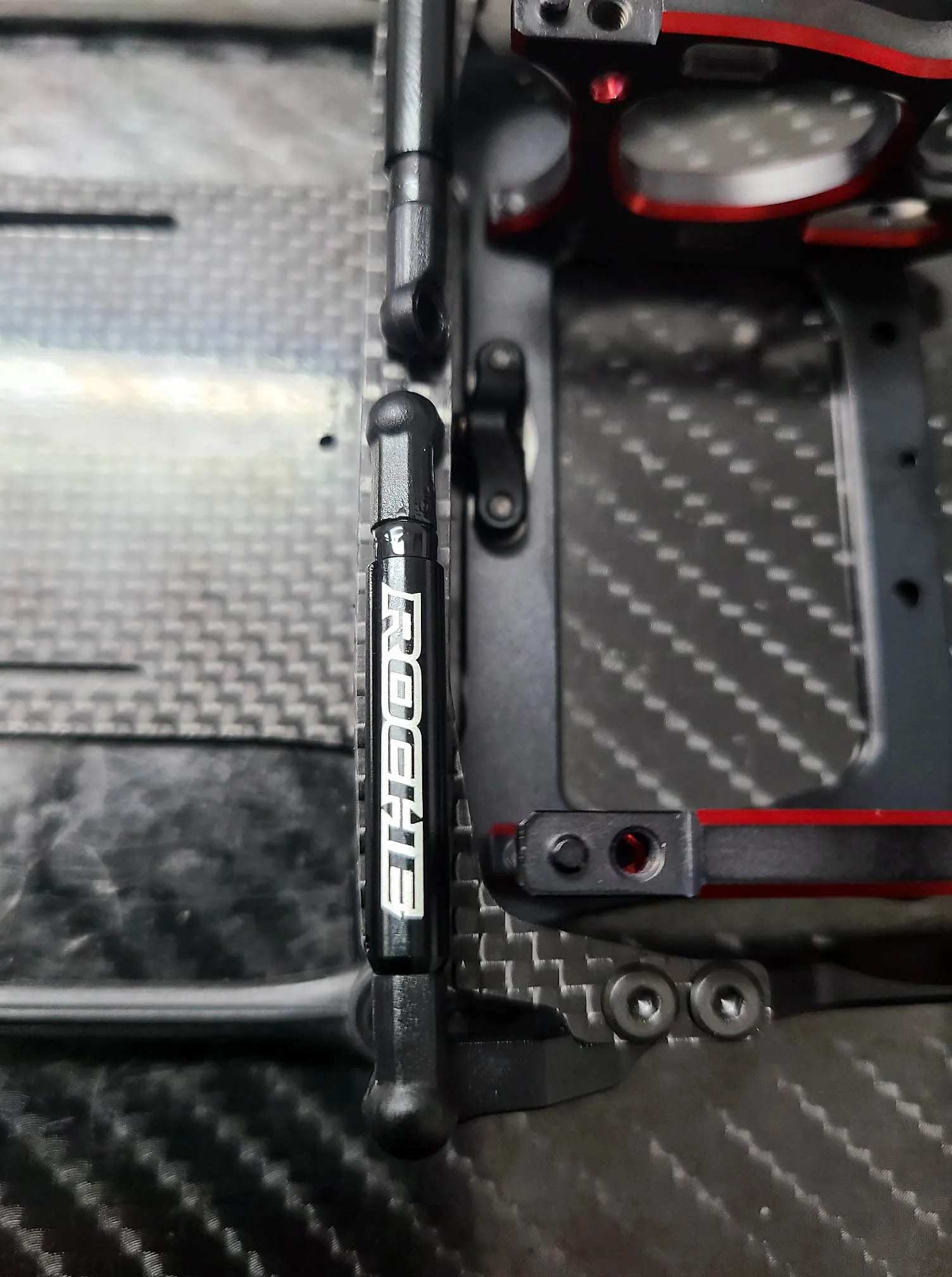
Just press the Tube with small amount of pressure to the ballstubs and next step is done. In this picture I can finally show you one thing I missed before. Every alloy part as an alignment pin next to the screws for perfect fit.
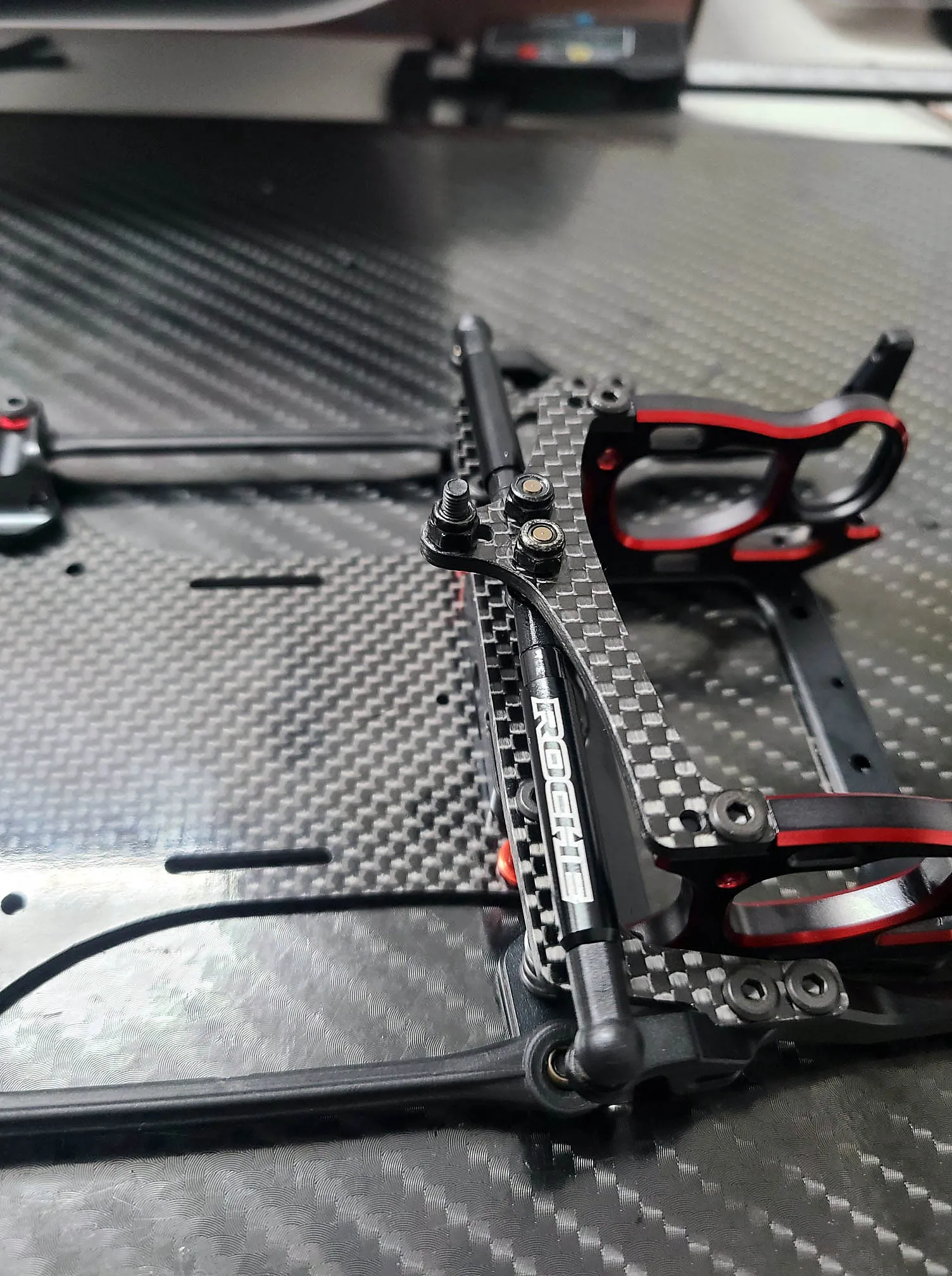
To finish this part of the Build process screw the top plate to the bulkheads and press the tubes to the premounted ball stubs.
Episode 7: We are mounting the last carbon parts and just two more episodes needed to finish the car. Next one will be the Shock Build and the last one is the build of the ball differential
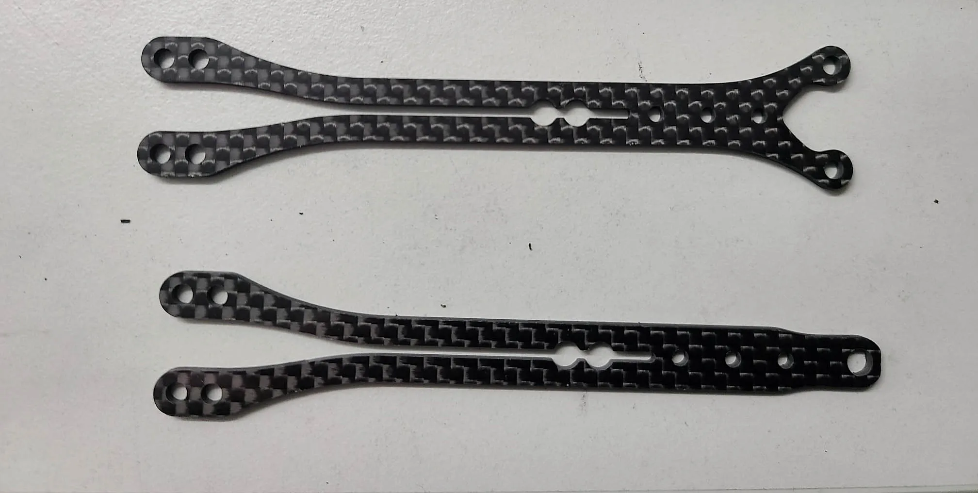
The Evo 3 brings us two new Topdecks. The Flex version on the left which is included in the kit and the harder version as an option Part. Its hard to say which one is better basicly I would say the soft one is usefull for outdoor racing and the hard one for indoor racing.
Something special and complete new for roche cars are the new Top deck screws to center every hole perfectly.
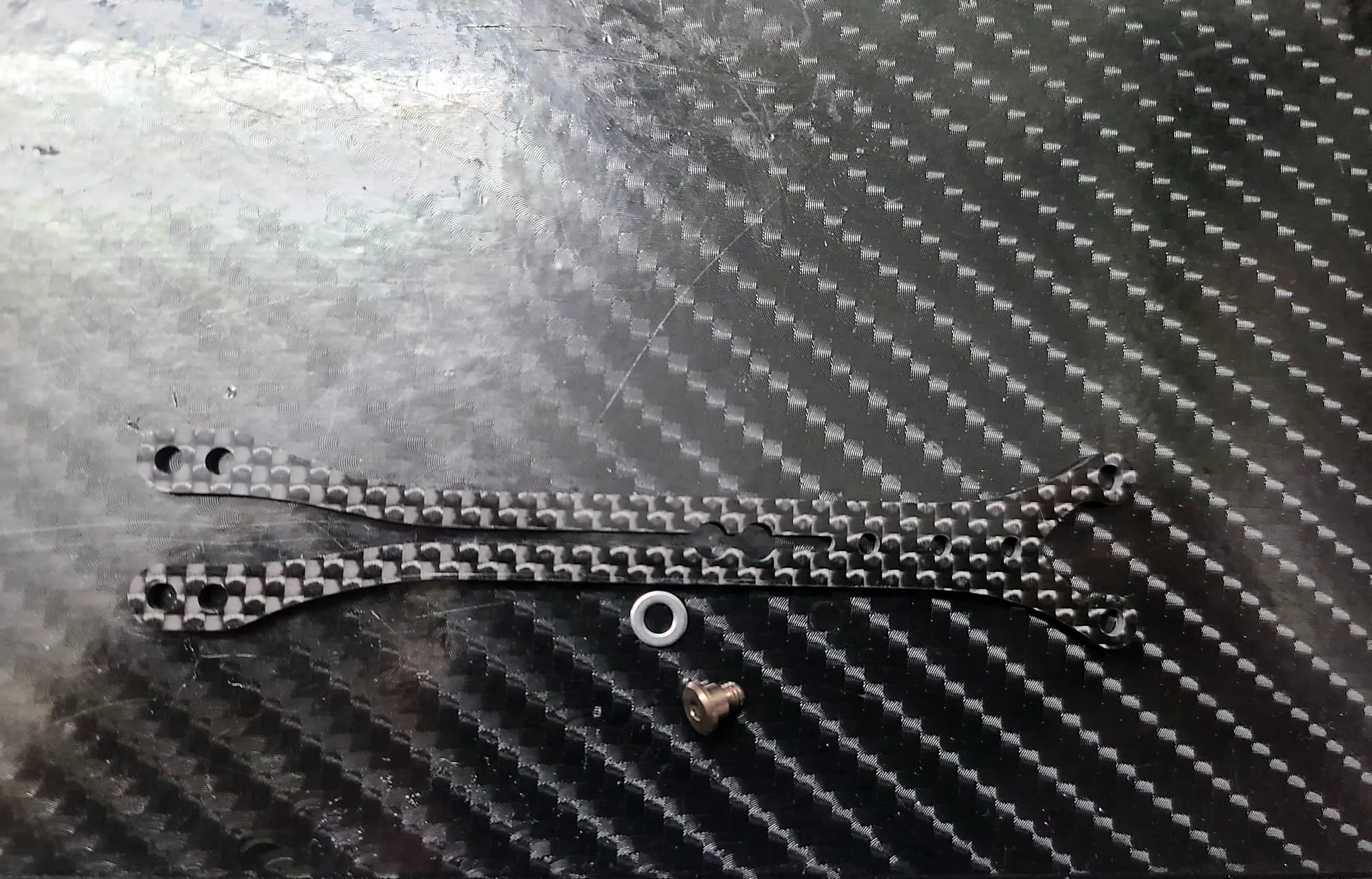
While mounting do not forget the thinn shims under the Topdeck.
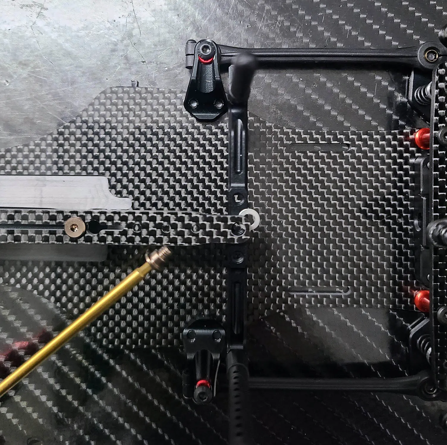
The old and known Battery plates from the Evo 2 are used in the Evo 3 too. We still have the option to move the Battery forward and backward easily with just changing the hole.
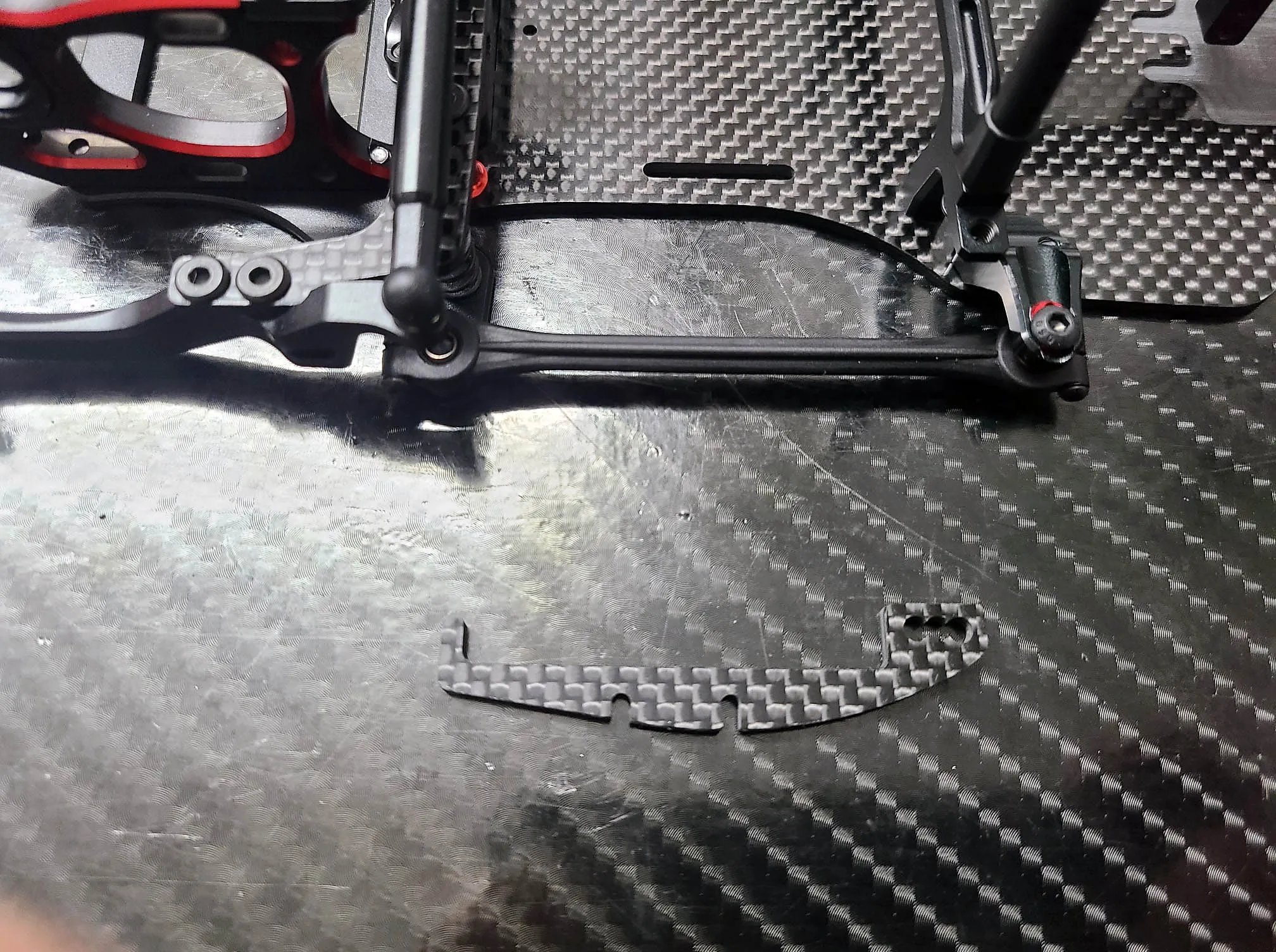
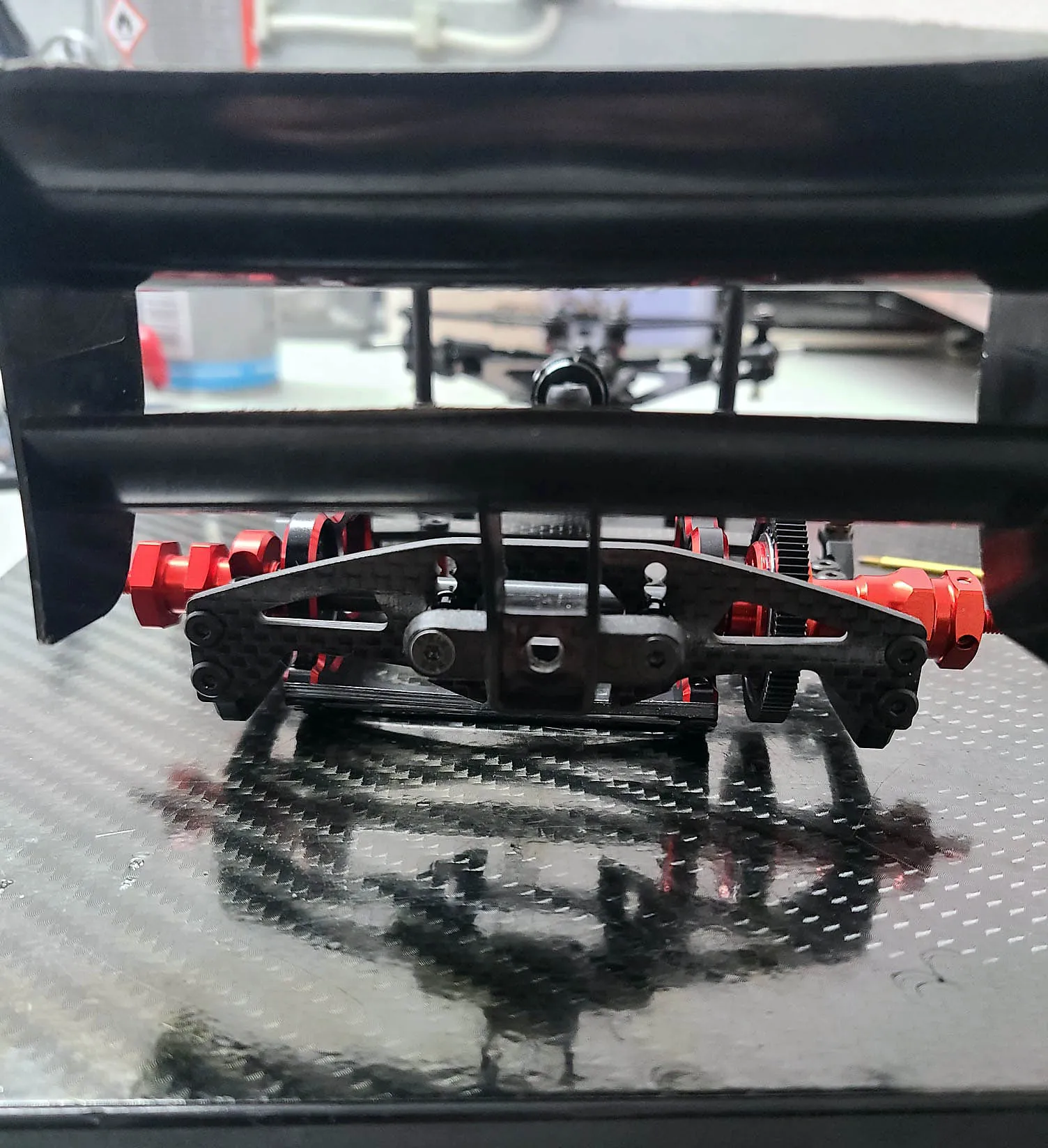
Last but not least this is the only carbon part left. Its the Rear wing plate. Since I'm working together with Roche I always use a post in front of the rear wing. I choose the Length of the post by amount of needed rear grip. If you ned more grip put the wing more backwards and if you want to reduce the Rear grip use a shorter one. Changing the height of the rear wing is possible like always before with the evo 3 but in my opinion you should put on the Body and choose the height of wing according to the end of the body for perfect airflow.
Episode 8 is about the center shock installation. I'm showing you how I personally build the shock and what options you have when you build it.
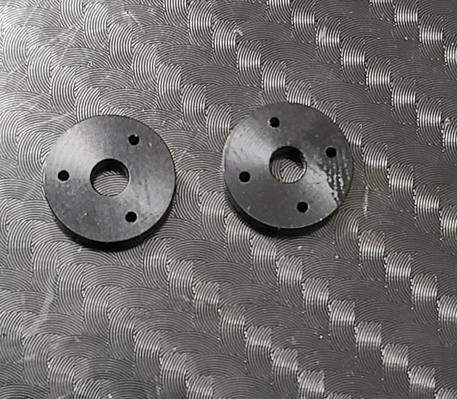
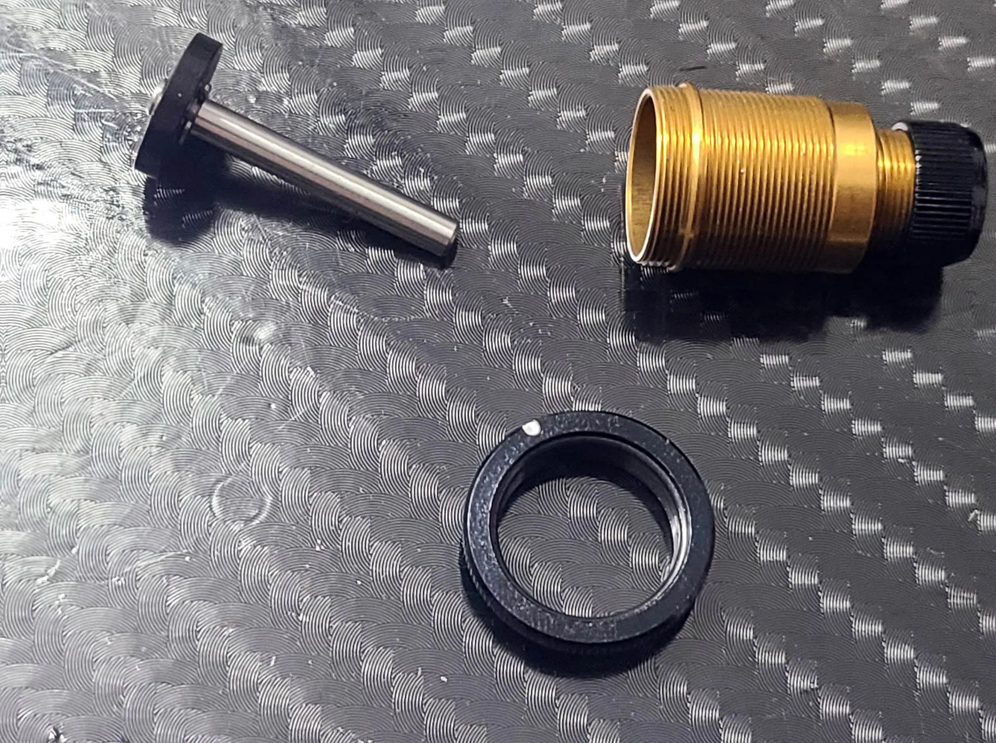
The first step of bulding the shock is to choose the piston and the amount of holes. If you want softer feeling you have to choose the 4 hole piston and for a harder feeling the 3 hole piston. In my opinion the 4 hole pistion the the part you should choose but sadly its an option part.
After choosing the Piston and press th e-clips onto the shaft I always put some oil to the o-ring and insert the o-ring into the slot of the nut.
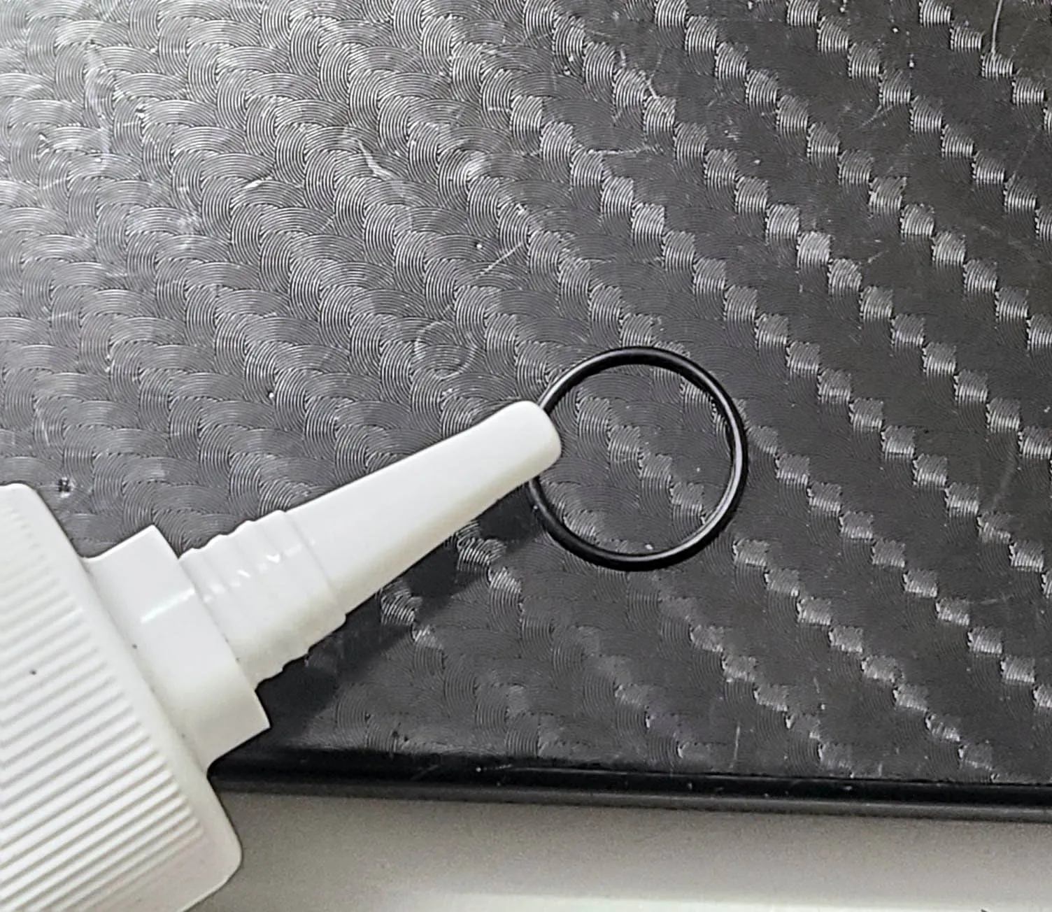
Before I continue with the shock I put the sealing O-ring into oil and wait for about one night. The O-ring will get slightly bigger and will prevent leaking.
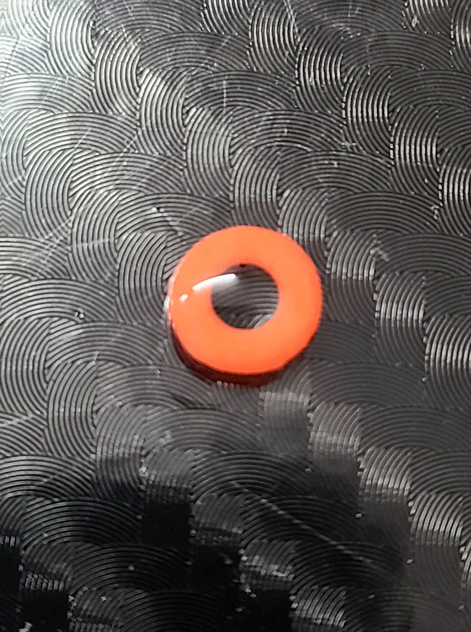
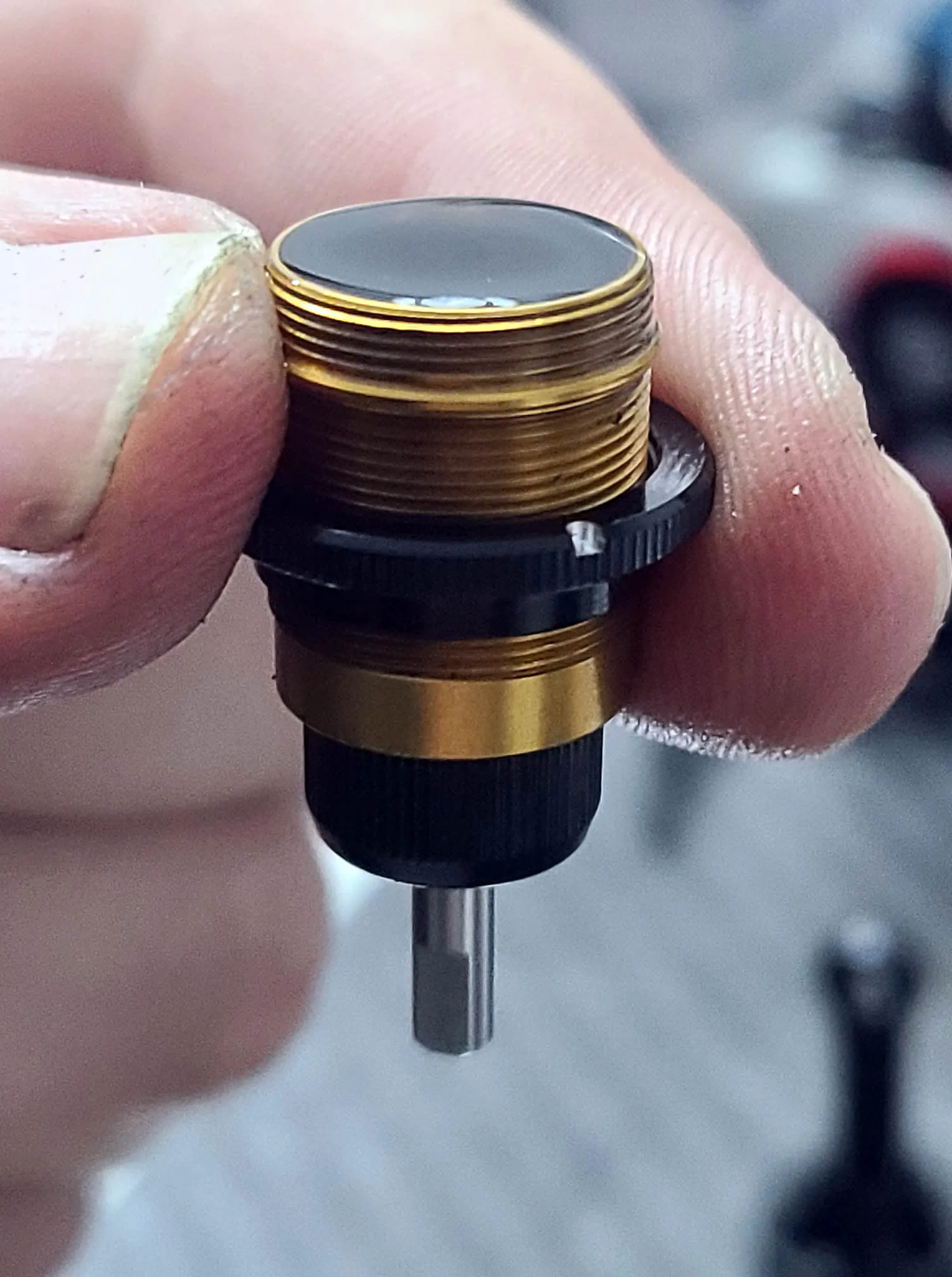
In this photo we see the O-ring already installed and the piston can be moved into the shock body. The bottom nut is just turned few times and not pressing the O-ring. After the shaft is inside we can tighten the bottom nut.
Filling up the Shock until the top of the body is what I do normaly. I have coosen 450 cst oil from MR33 for this shock.
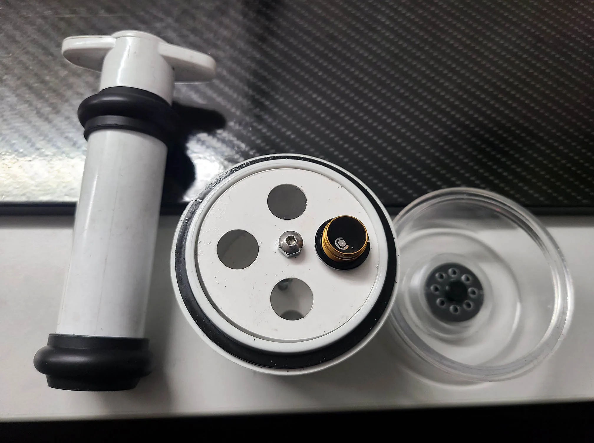
Before I put the shock into the vacuum pump I move the shaft up and down a few times to let the bubbles of air out.
The last step is to close the shock with top cap when the shaft is moved into the shock and just the bevel can be seen.
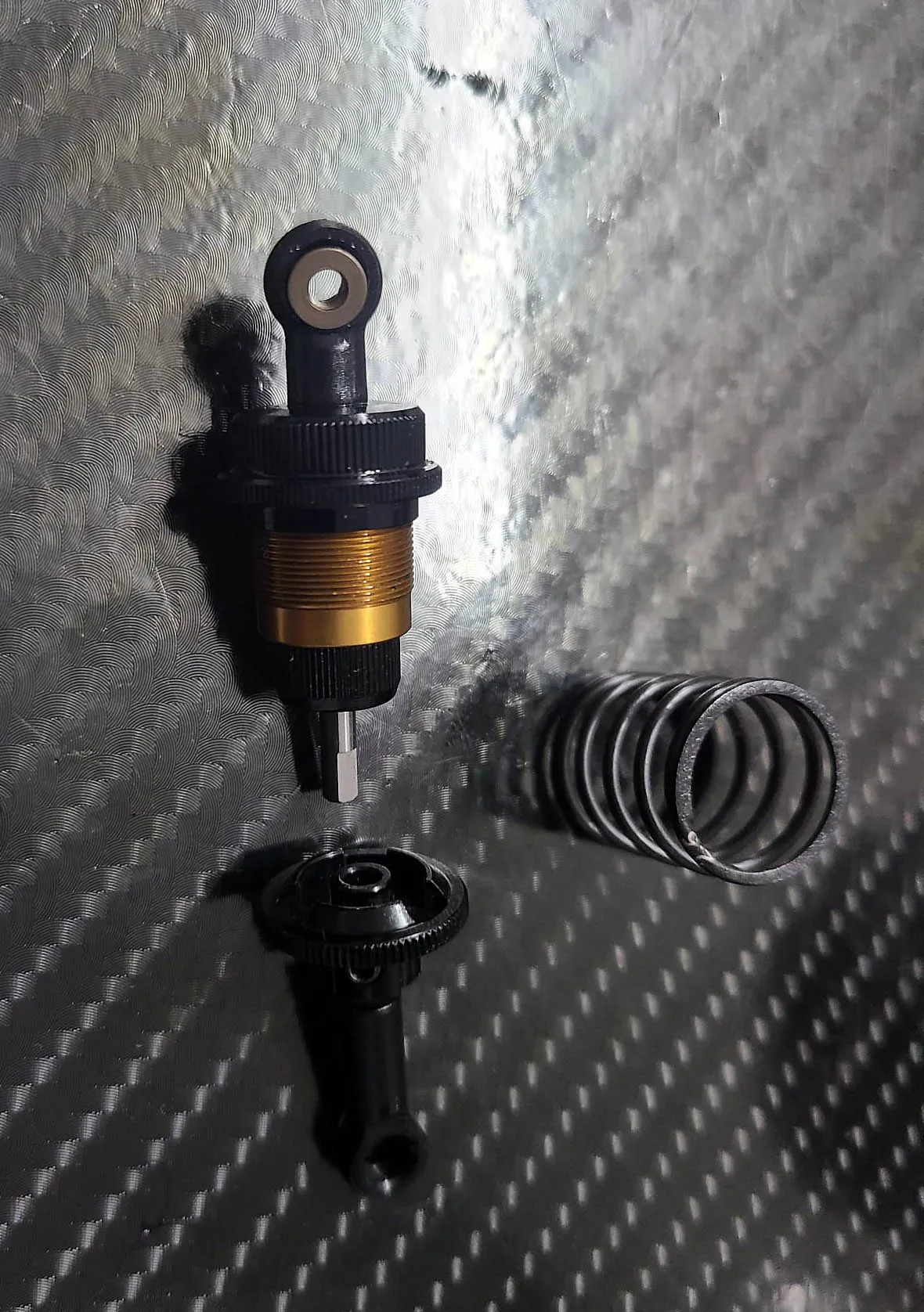
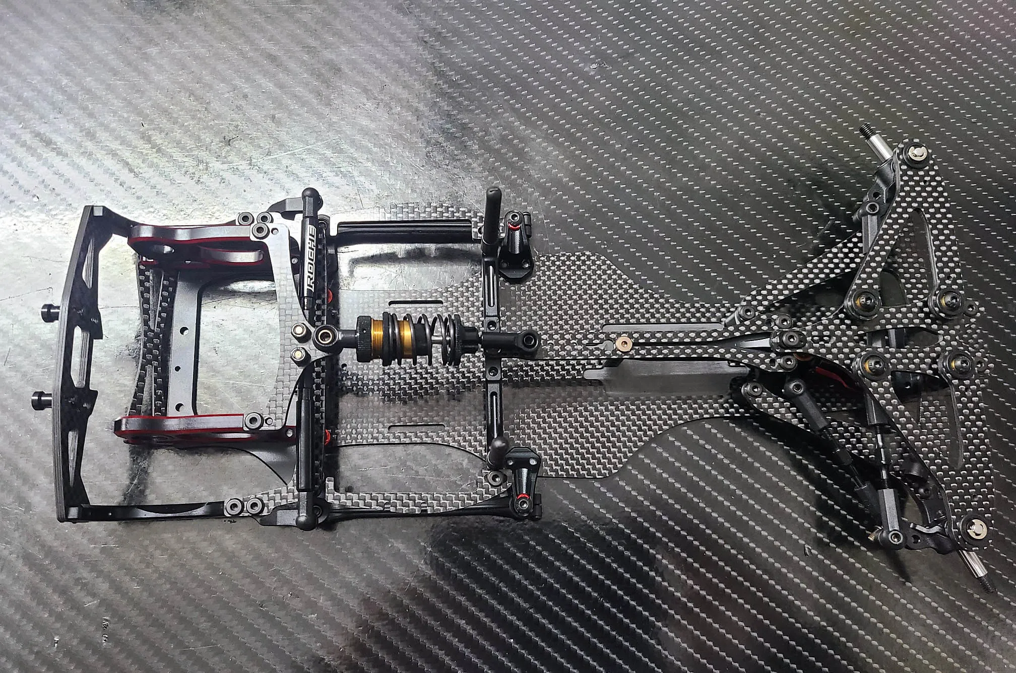
The bottom part of the shock is the last thing I do and I show ou today. The Part has two setup options and you can choose the length of the shock. Long version needs the extender of the ballcup and short version just the ballcup. With both options you can still fine tune the droop when you turn the bottom part of the shock like a screw.
Car is basically finish after installing the shock just the differential is missing. How to build the differential is the Topic of the last episode.
Episode 9: Ball diferential
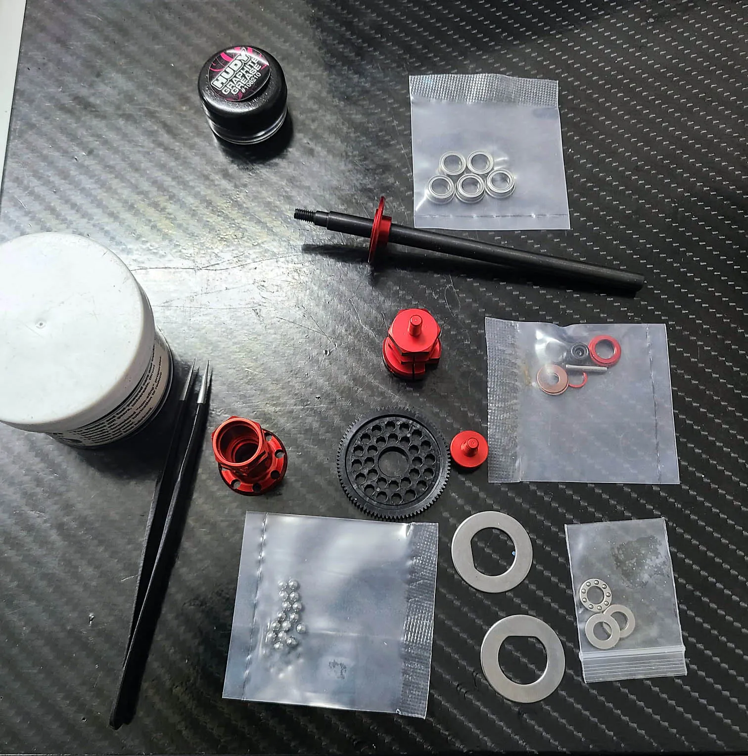
These things are all i use to build a ball diff. Expet the graphite grease and the diff grease everything is in the kit
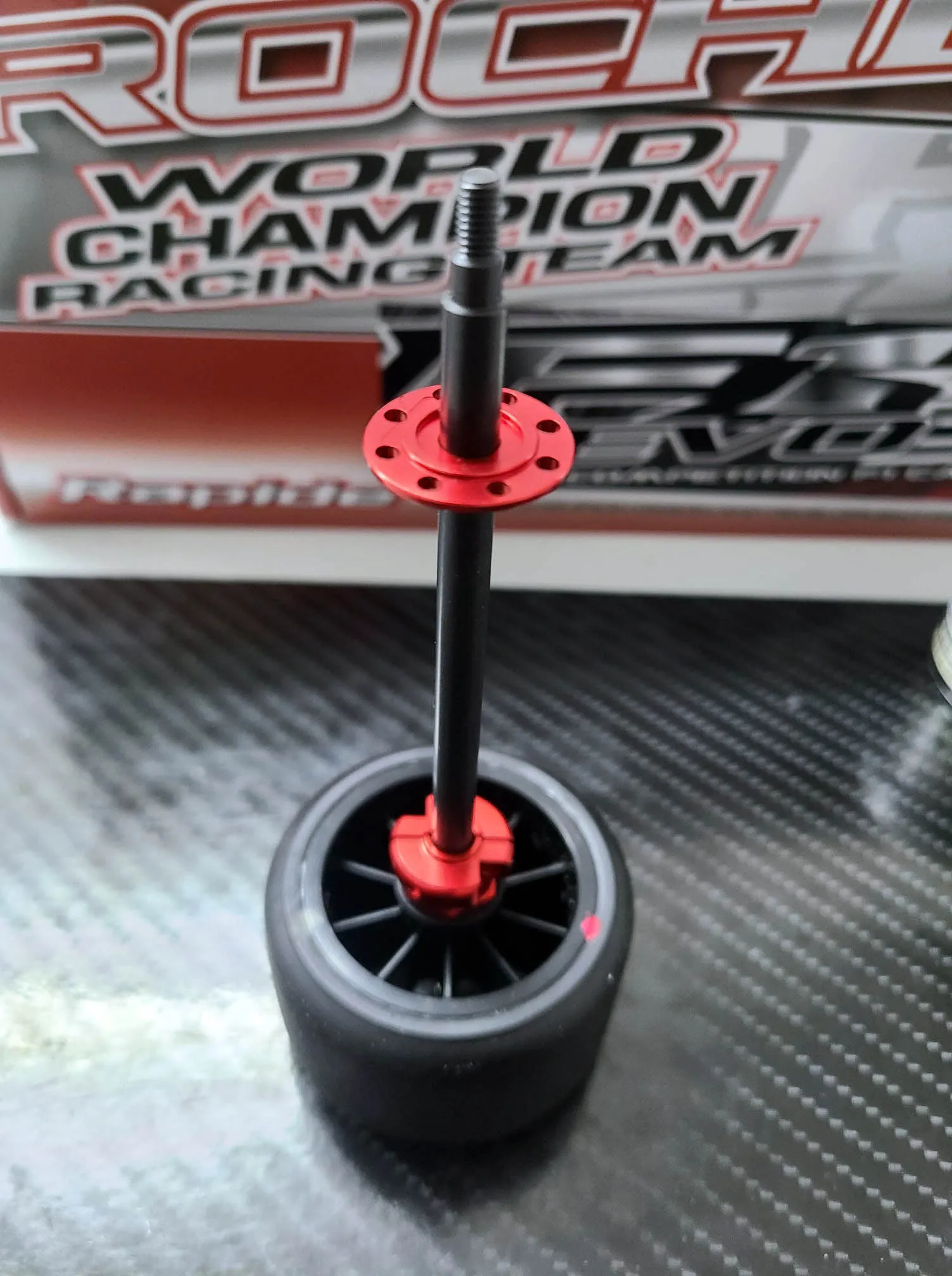
For easier building i take out a rear set of tires and put the rear axle inside.
The first thing i do is to put a very small amount of grease to the red rear axle plate.
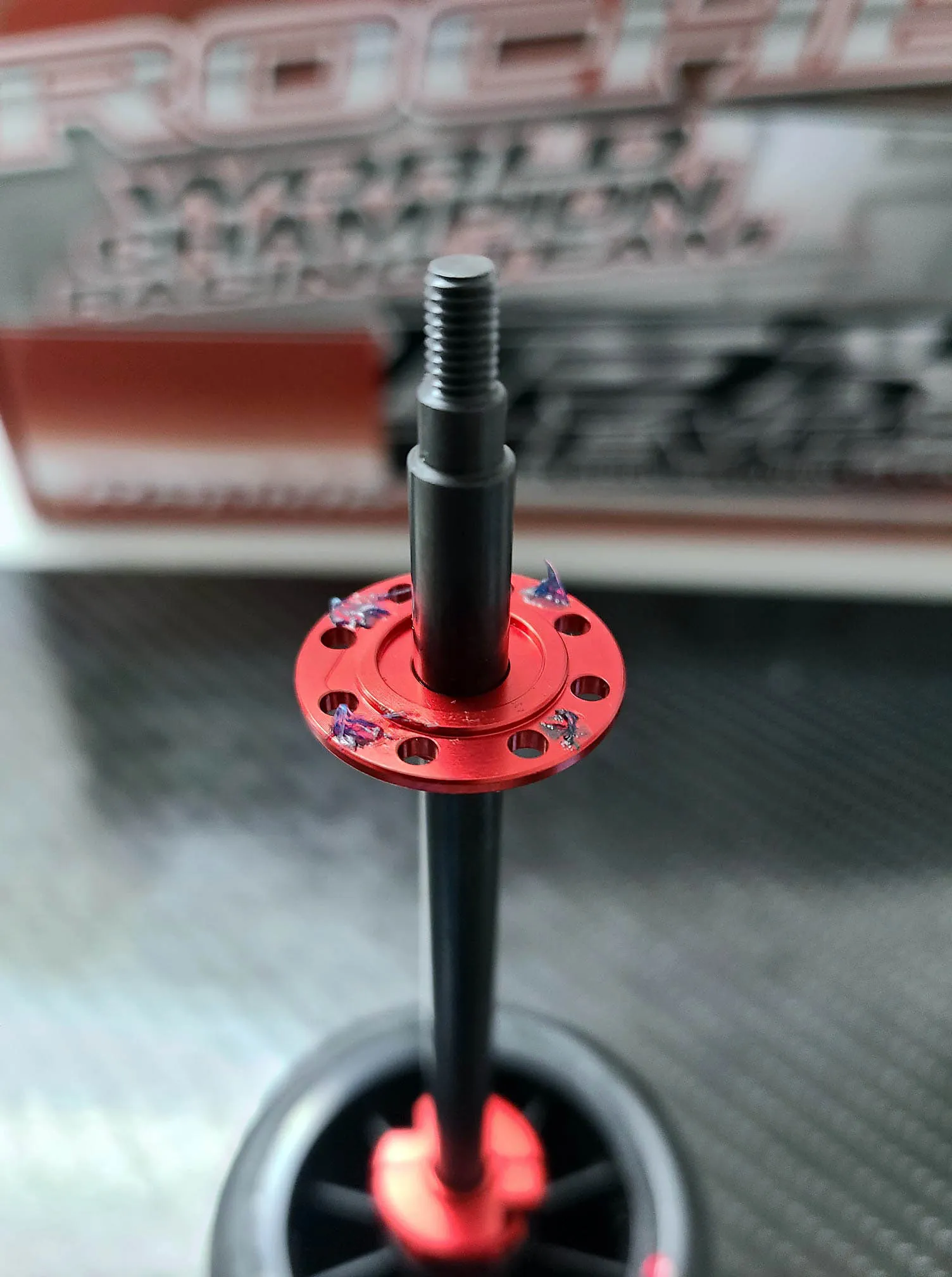
The reason why i put the grease there shows this picture just in case you have a crash with your diff on the table the diff plate does't fall off.
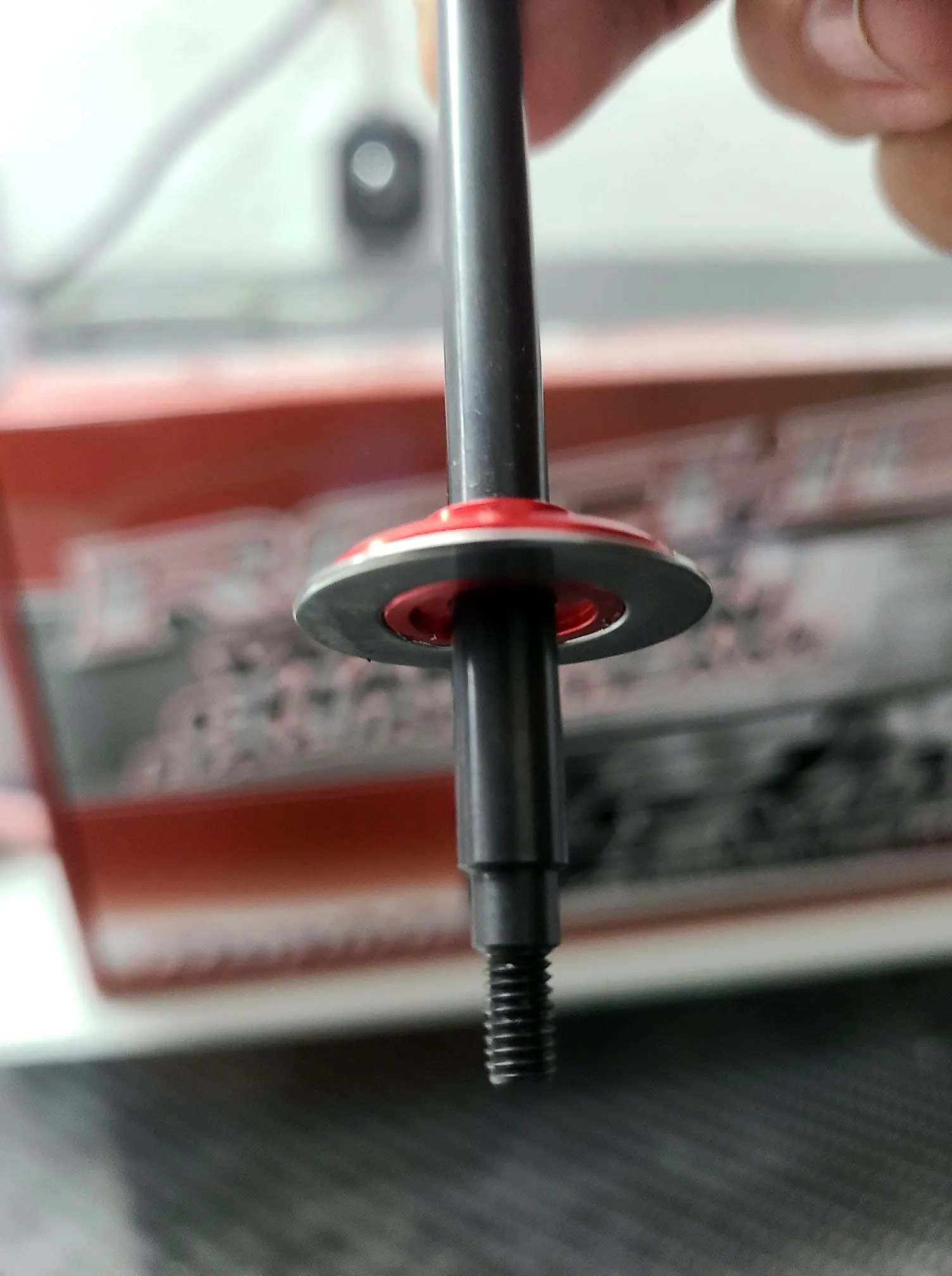
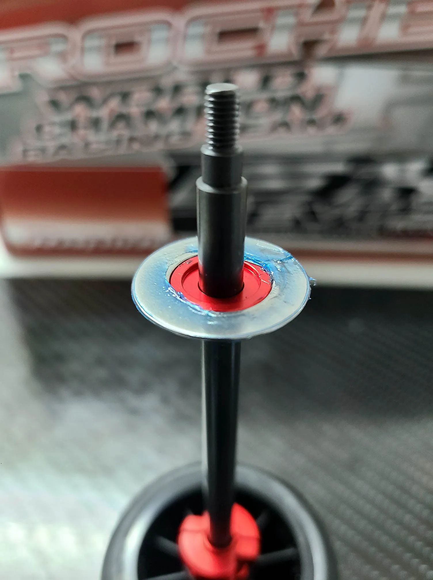
Next step is apply a very thin film of diff grease onto the diff plate.
As a spur gear i always choose a 88T 64p from Xenon/ Roche because you get the maximum Gear ratio range for big and small Tracks.
I use a small tweezer for inserting the balls into the spur gears as you can see.
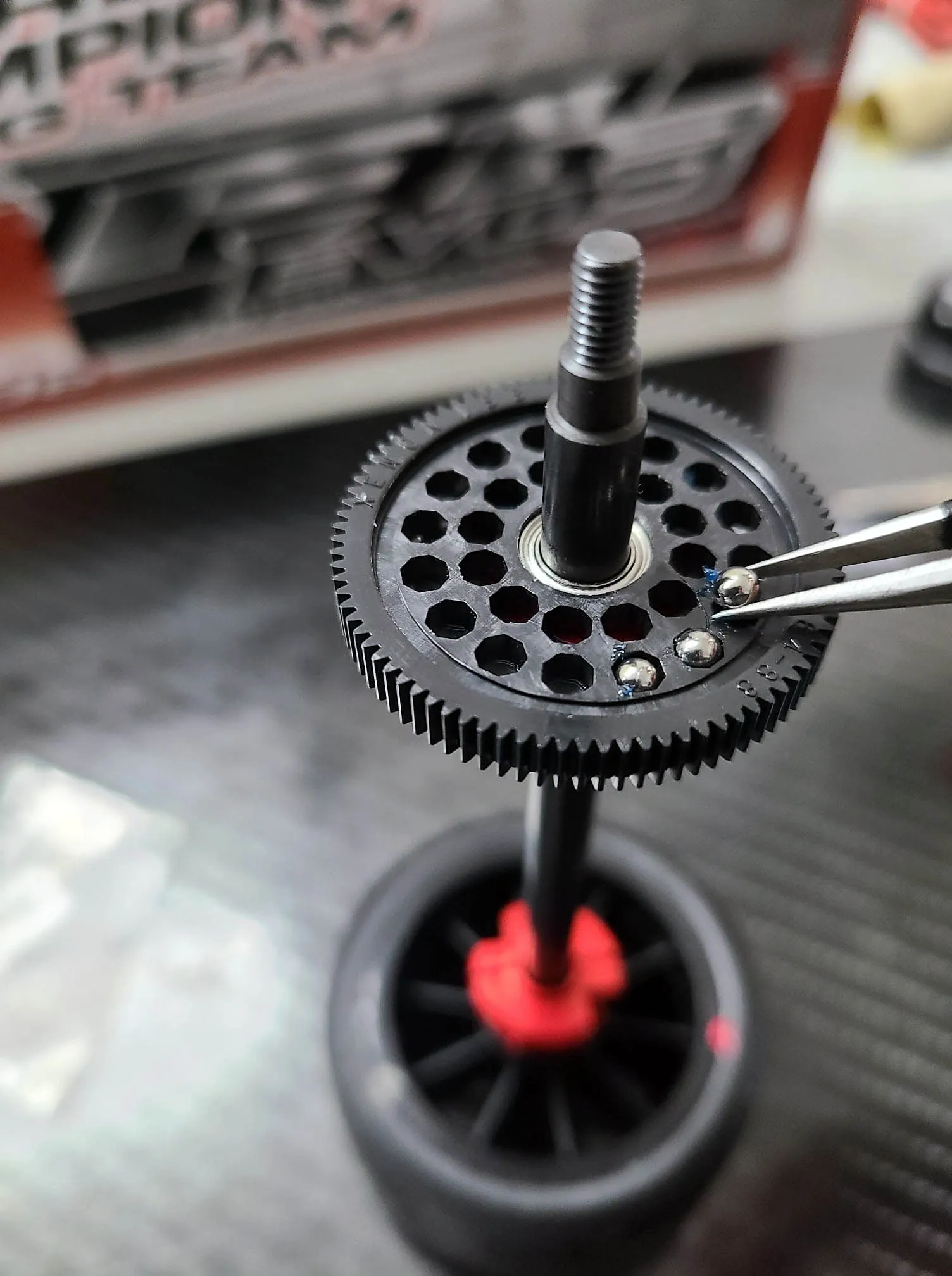
Applying the same thin film of grease has to be done on the other side too.
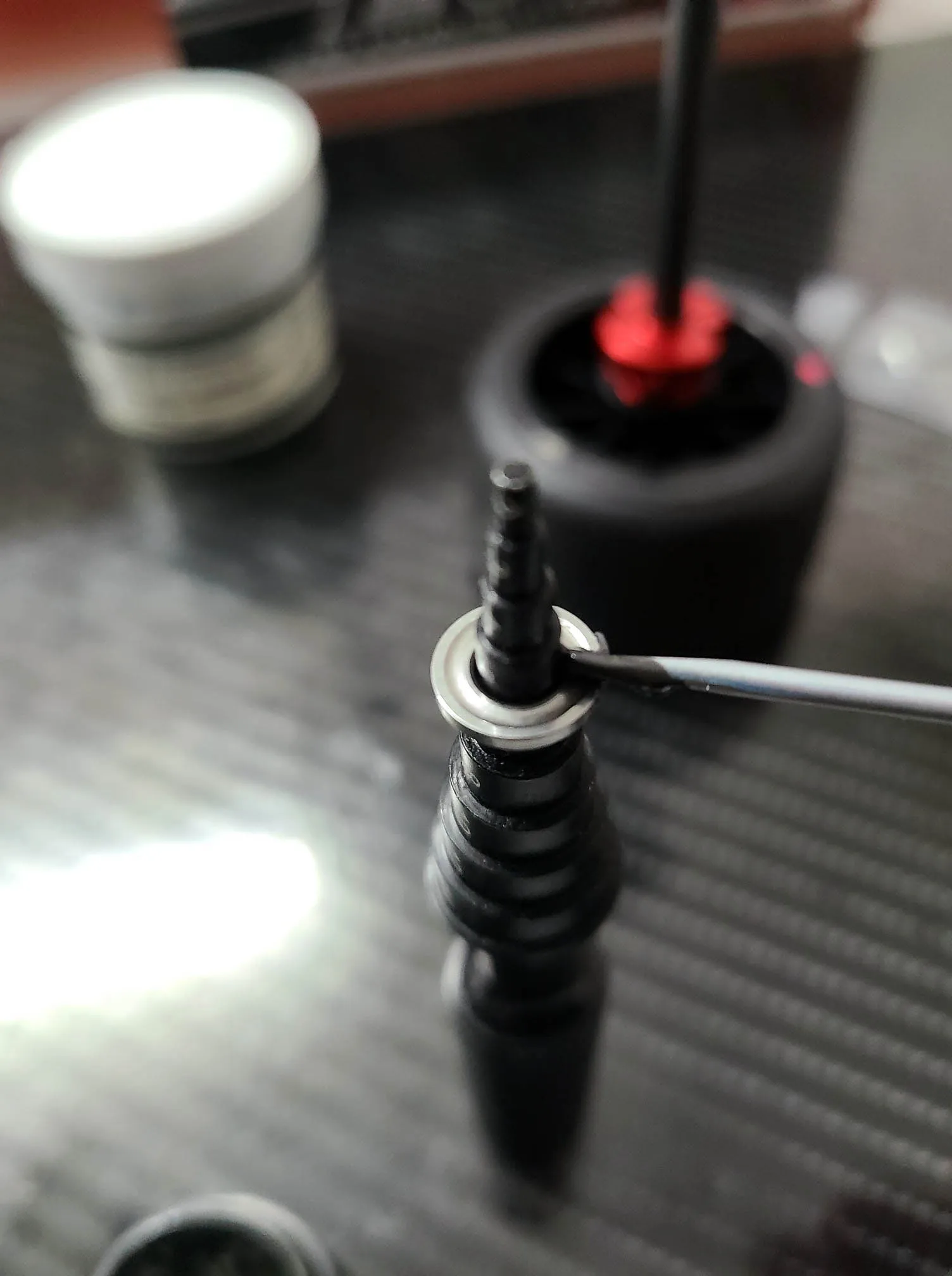
Now we come to the thrust bearing. I use the MR33 bearing holder to prepare the thrust bearing. I put a small amount of black graphite grease to the top off the shim.
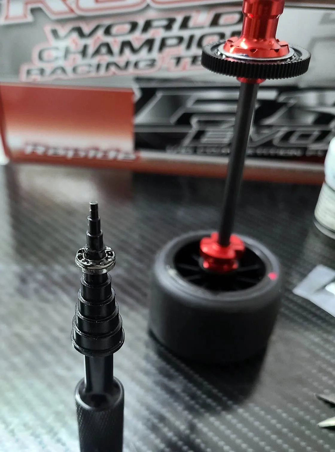
The main ball cage follows on top of the shim. There i apply some black grease too.
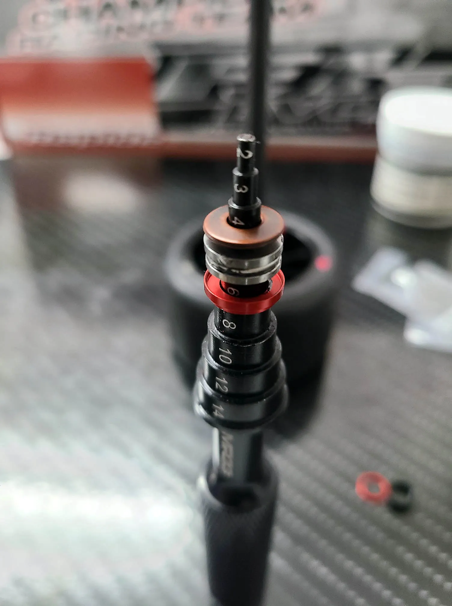
To finish the thrust bearing we just need to add the Belleville washer on top of all
To adjust the hardness of the diff you can use the same screwdriver as you use for mounting the tires. A soft diff should be used on low grip and a harder or better a more closed diff on high grip.
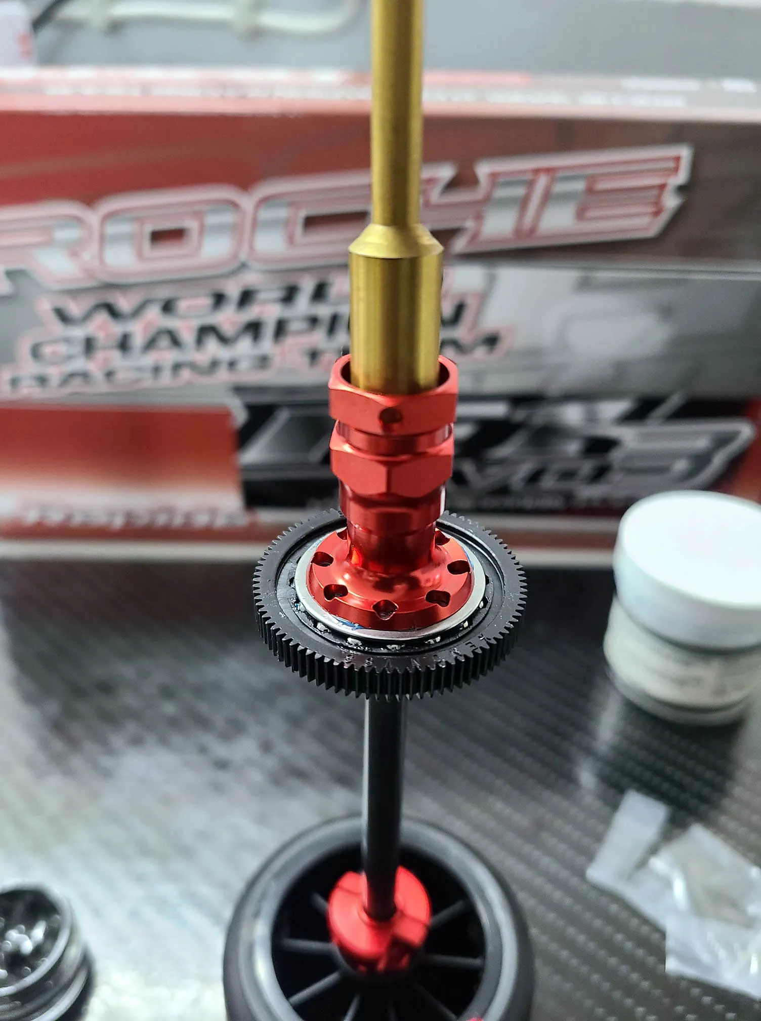
To close the diff and prevent the bearings to get dusty we need 3 small pieces.
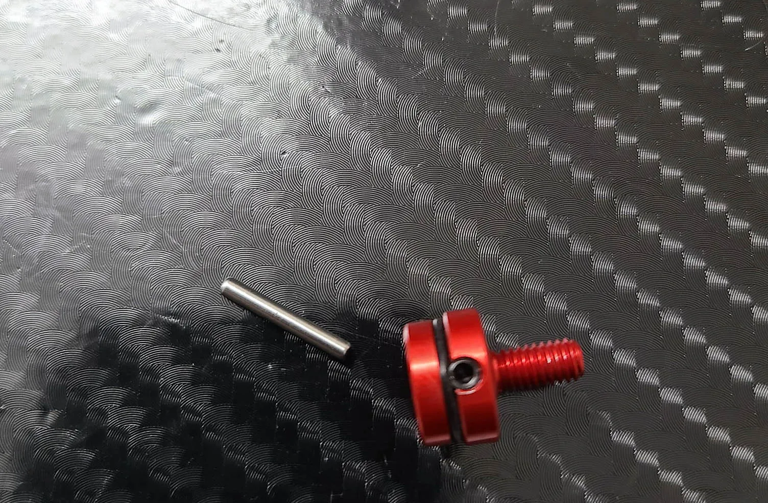
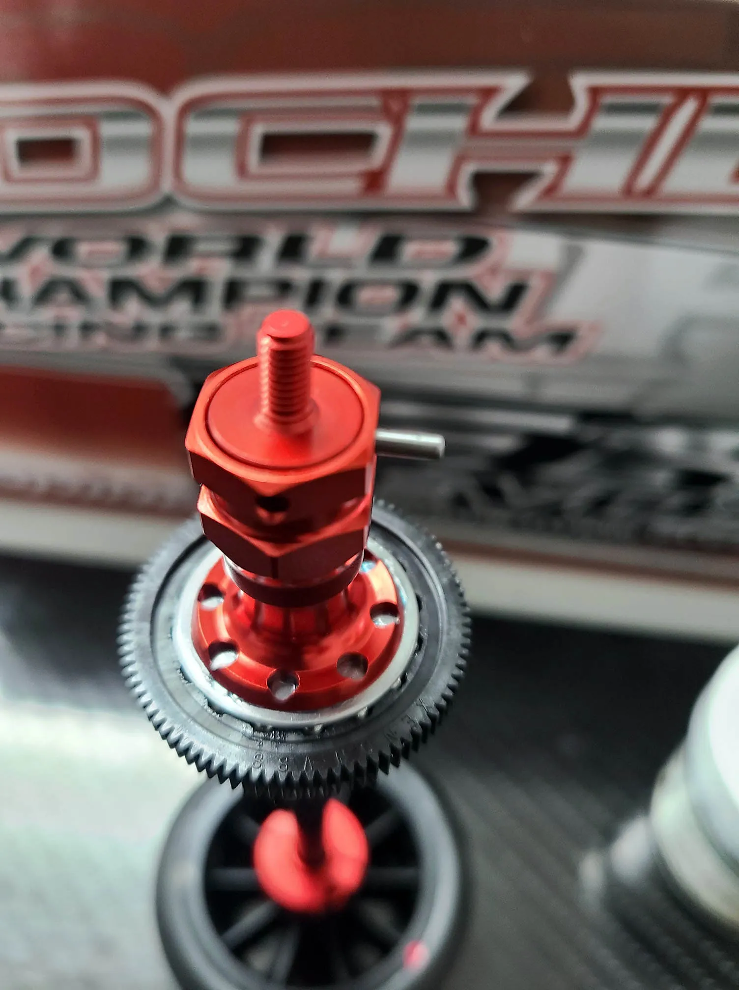
First thing to do is screw in the grub screw and put in the black o-ring. The grub screw just needs to be on the same heigt as the red alloy. The silver pins has to be inserted into the two smaller holes and secured with tightening the grub screw.
In this pictures we see the needed shims for align the Rear axle to center. If you add shims add them in the same amount on each side and you can increase the track width with it.
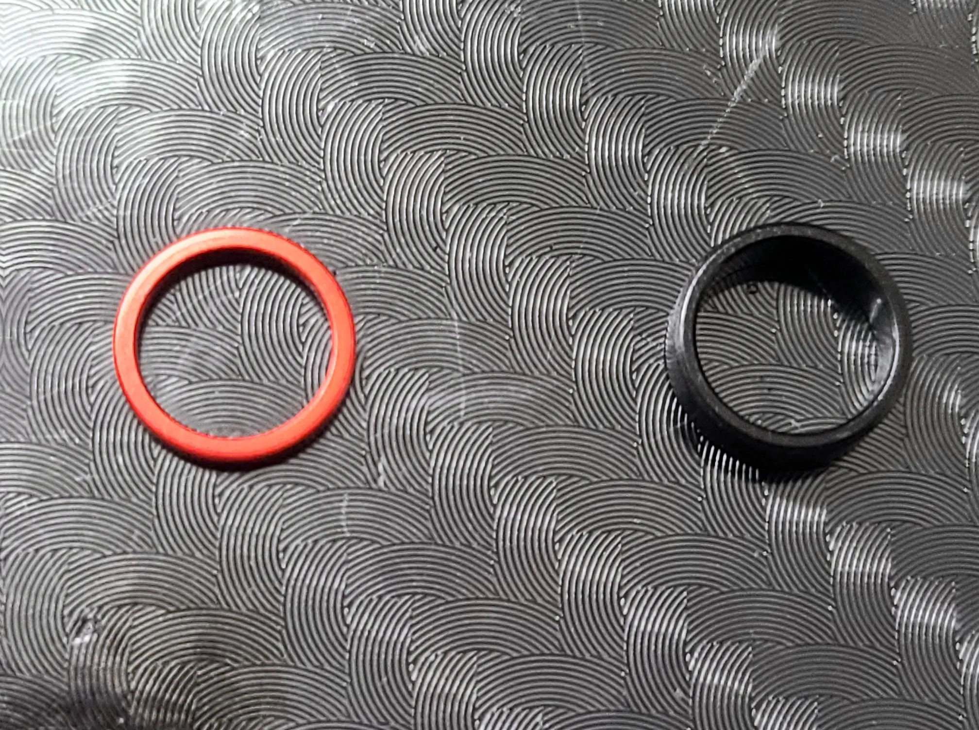
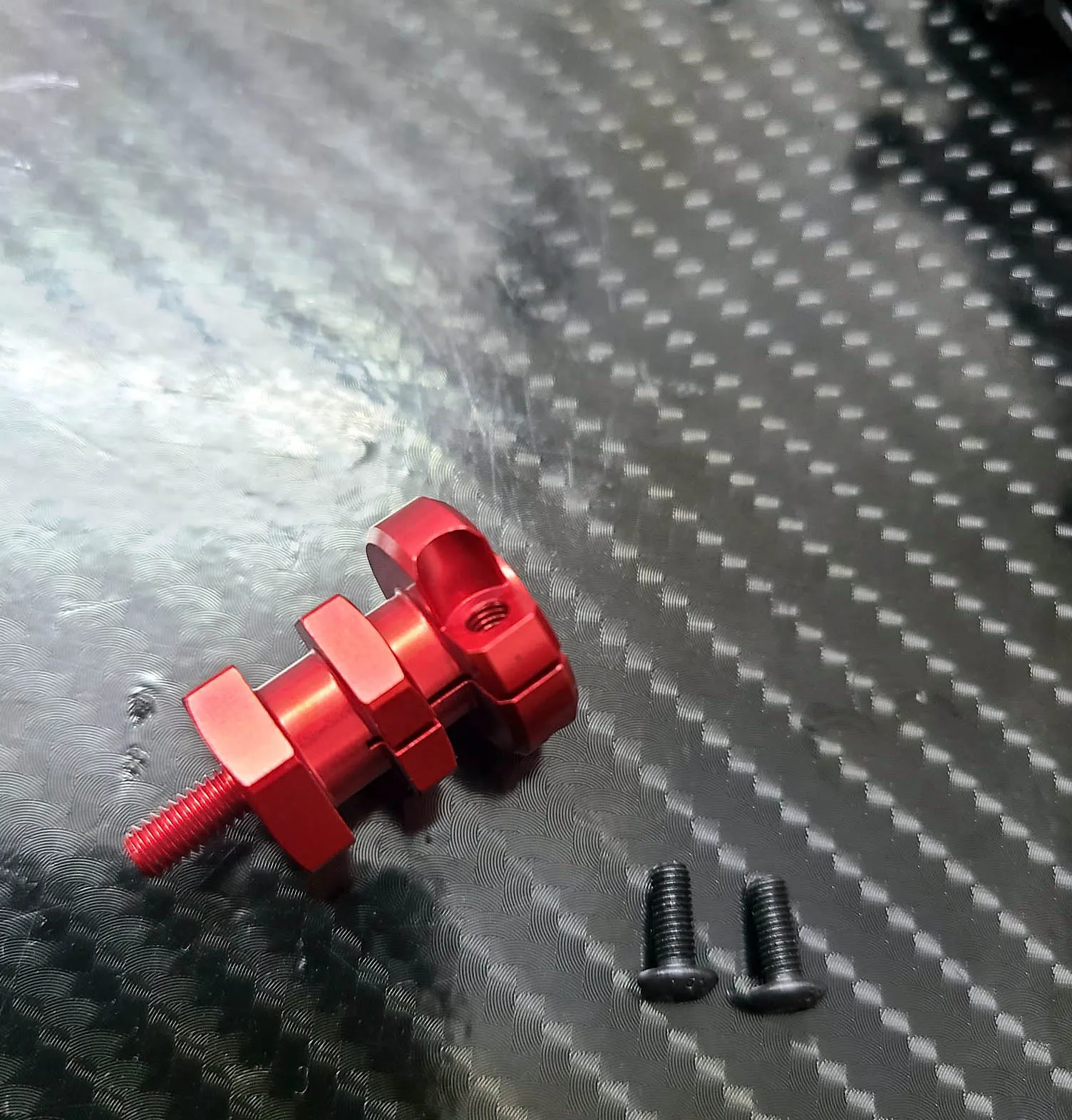
The red one has to be on the diff side and the bigger black one on the other side.
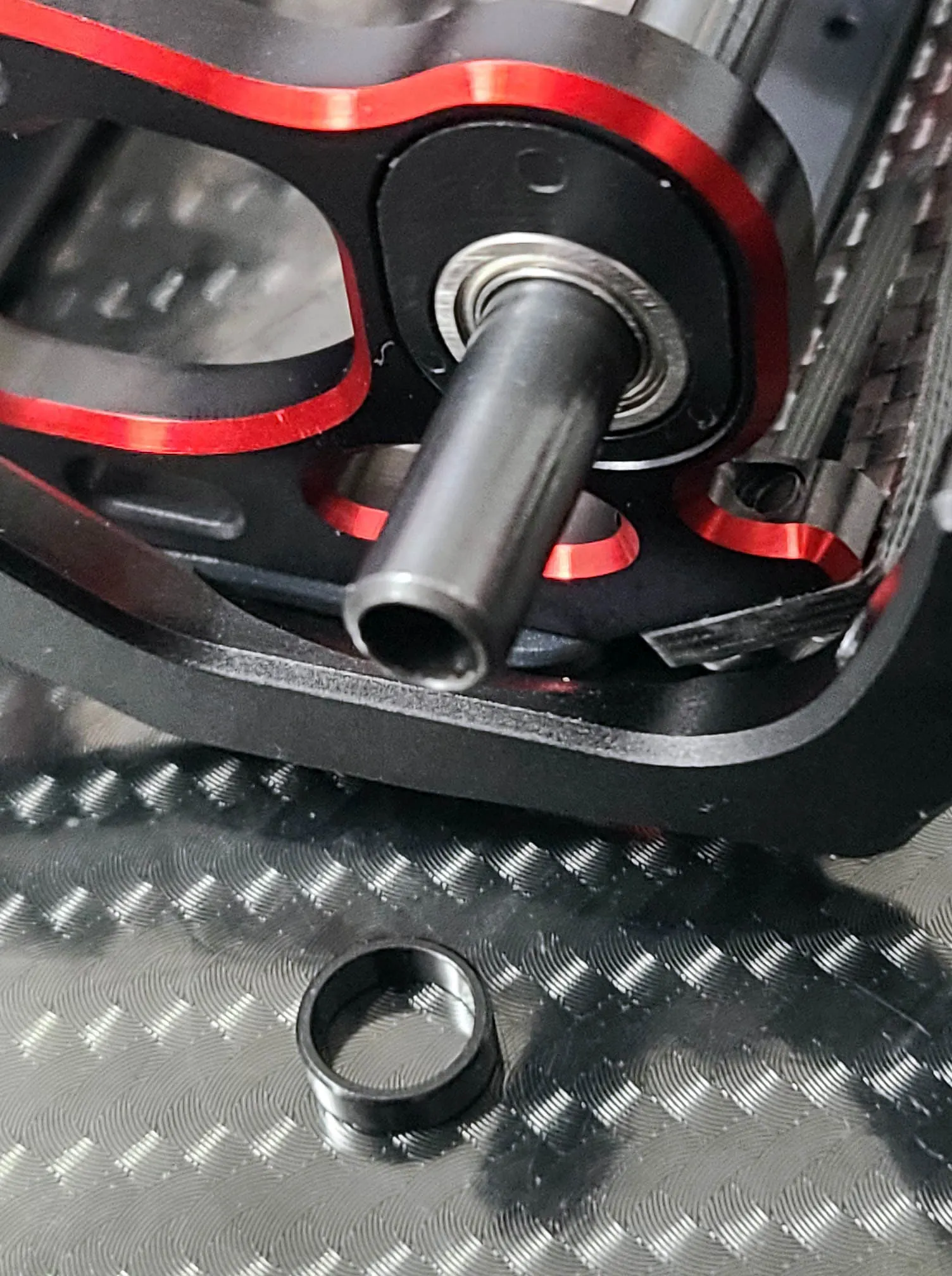
To secure the rear axle use two screws an carefully tightening them. Take a look if the gap on the red hub is the same on each side. Is the gap same you can go to the next step othwerise you need to unscrew the side with small gap and tighten the one with the big gap.
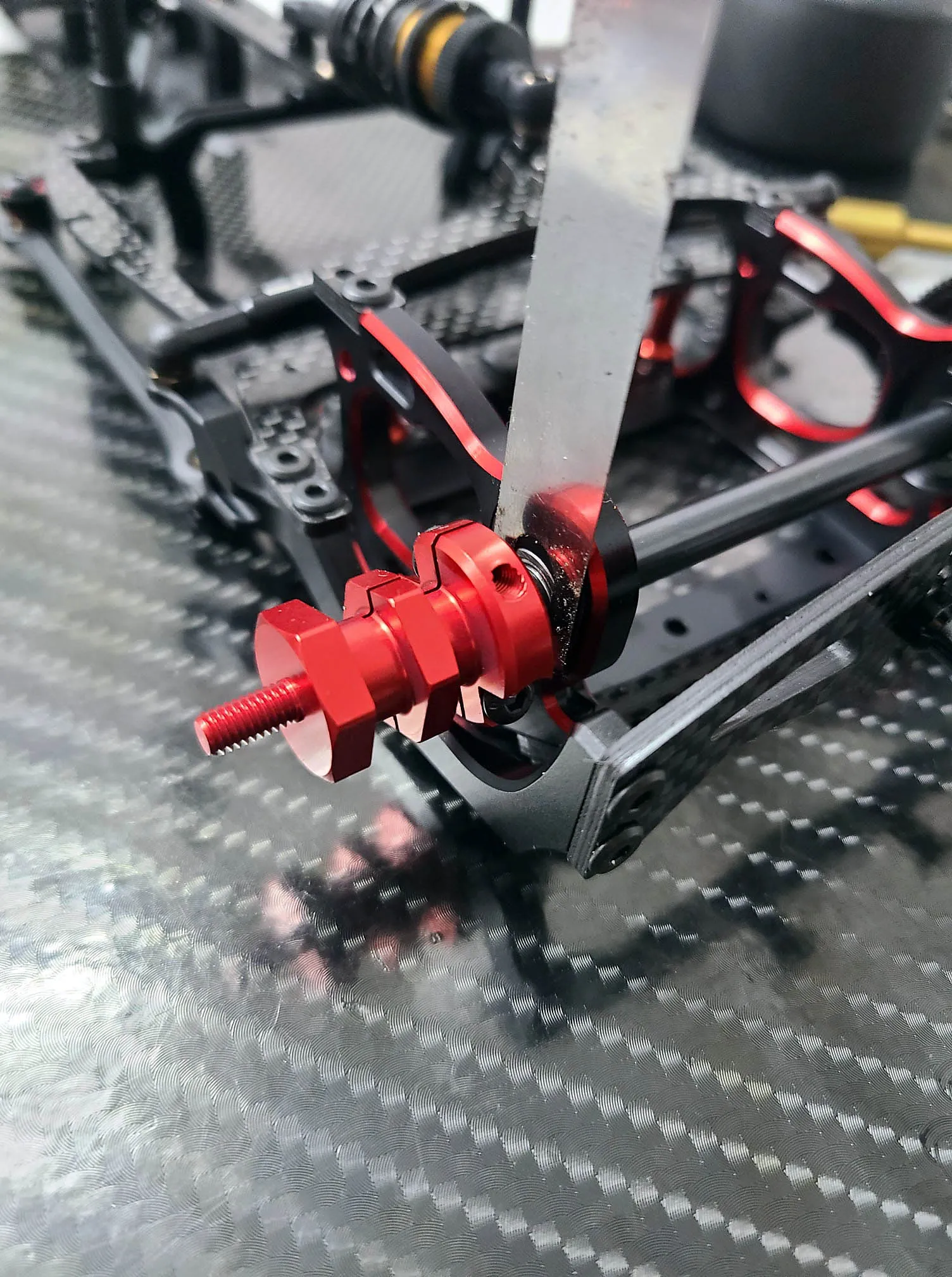
If you put the hub onto the rear axle do not press the hub against the bearings. Give the rear axle some space to work but not to much. I personally use a thin metal sheet of 0.1mm between the hub and the bearing when putting all together.
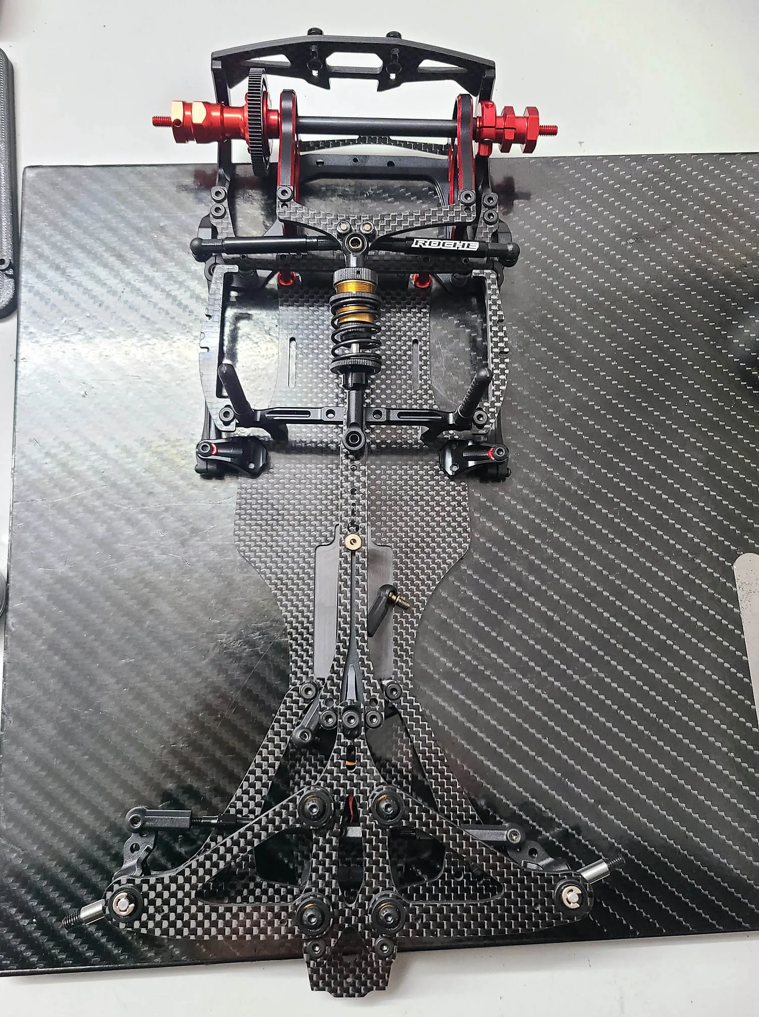
Car is normally finished but wings are missing.
Last steps are to mount the wings. I'm choosing a high downforce wing for rear in the most conditions.
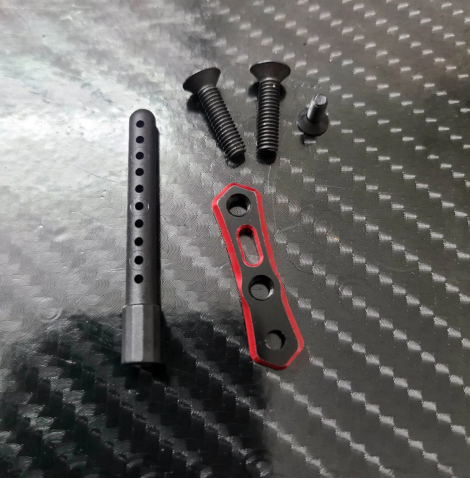
This small option part is very useful if you like to change the front wing and not to have 5-6 holes for every different wing on the market. The body post stays at the same place and the wing doesn't matter anymore.
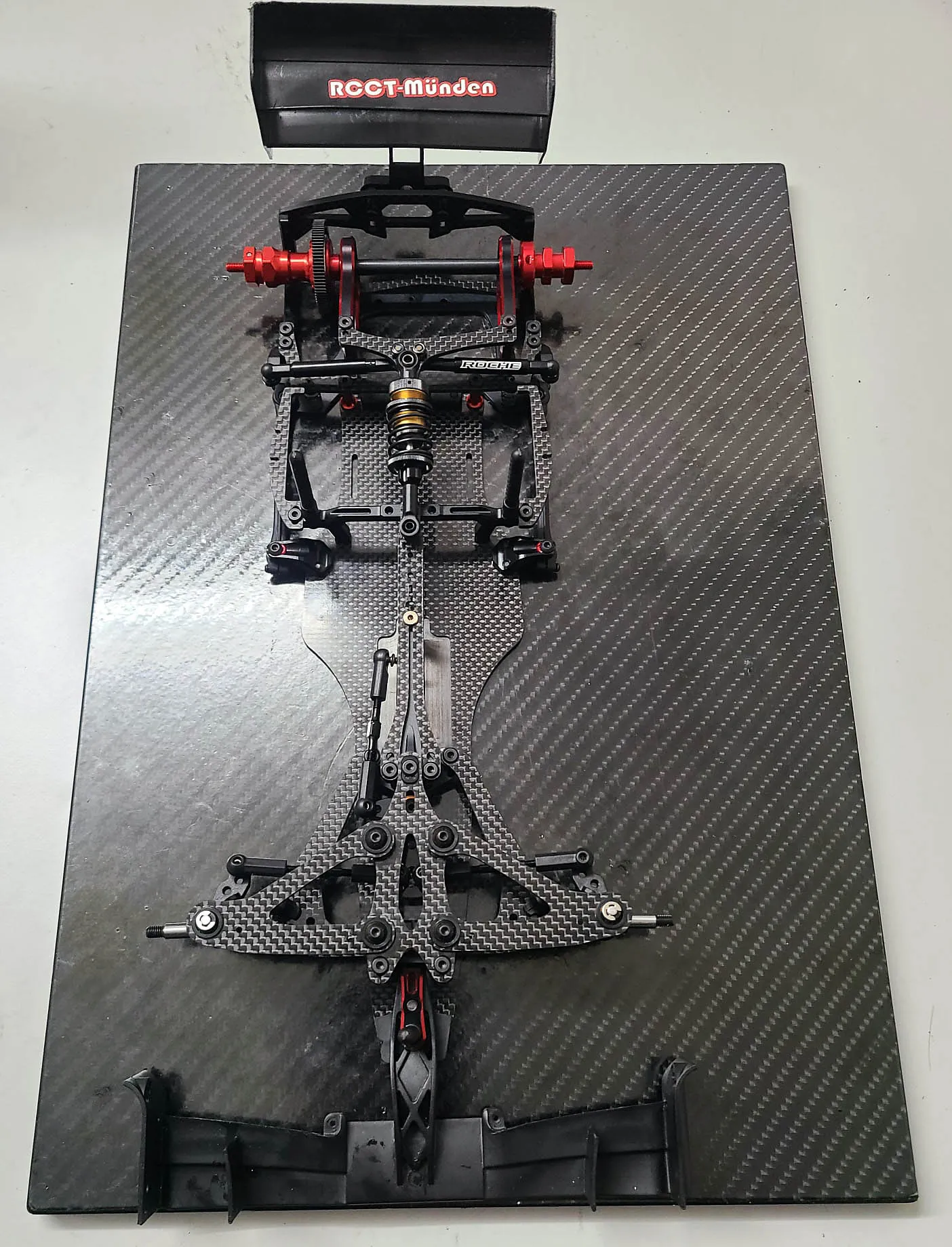
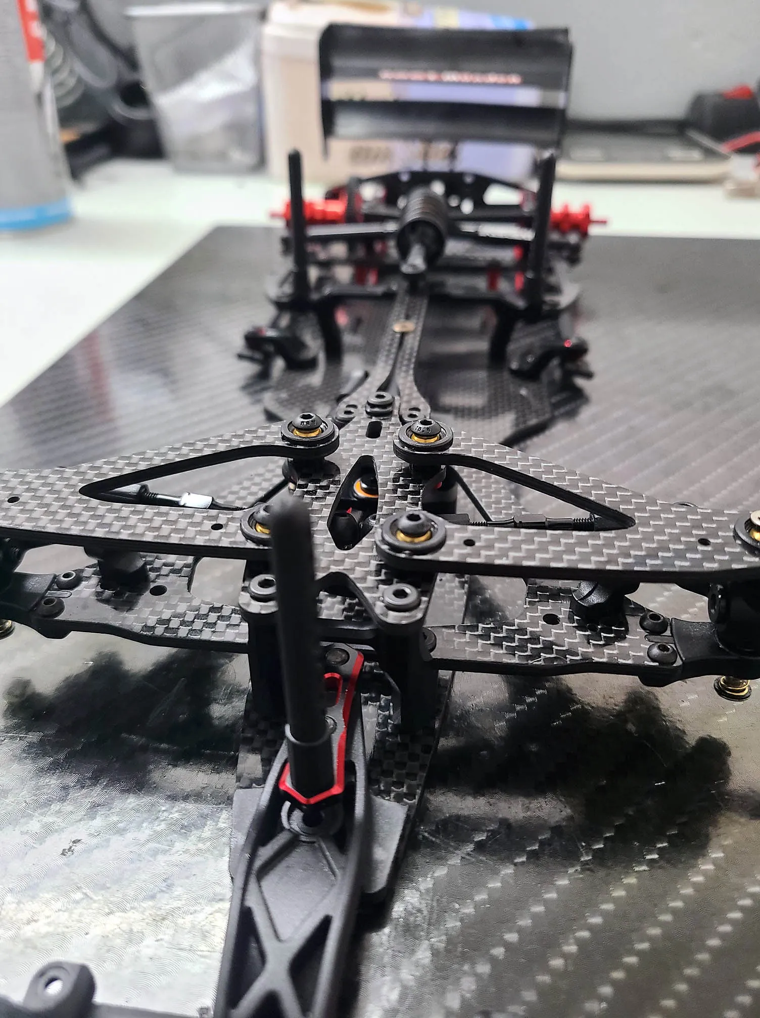
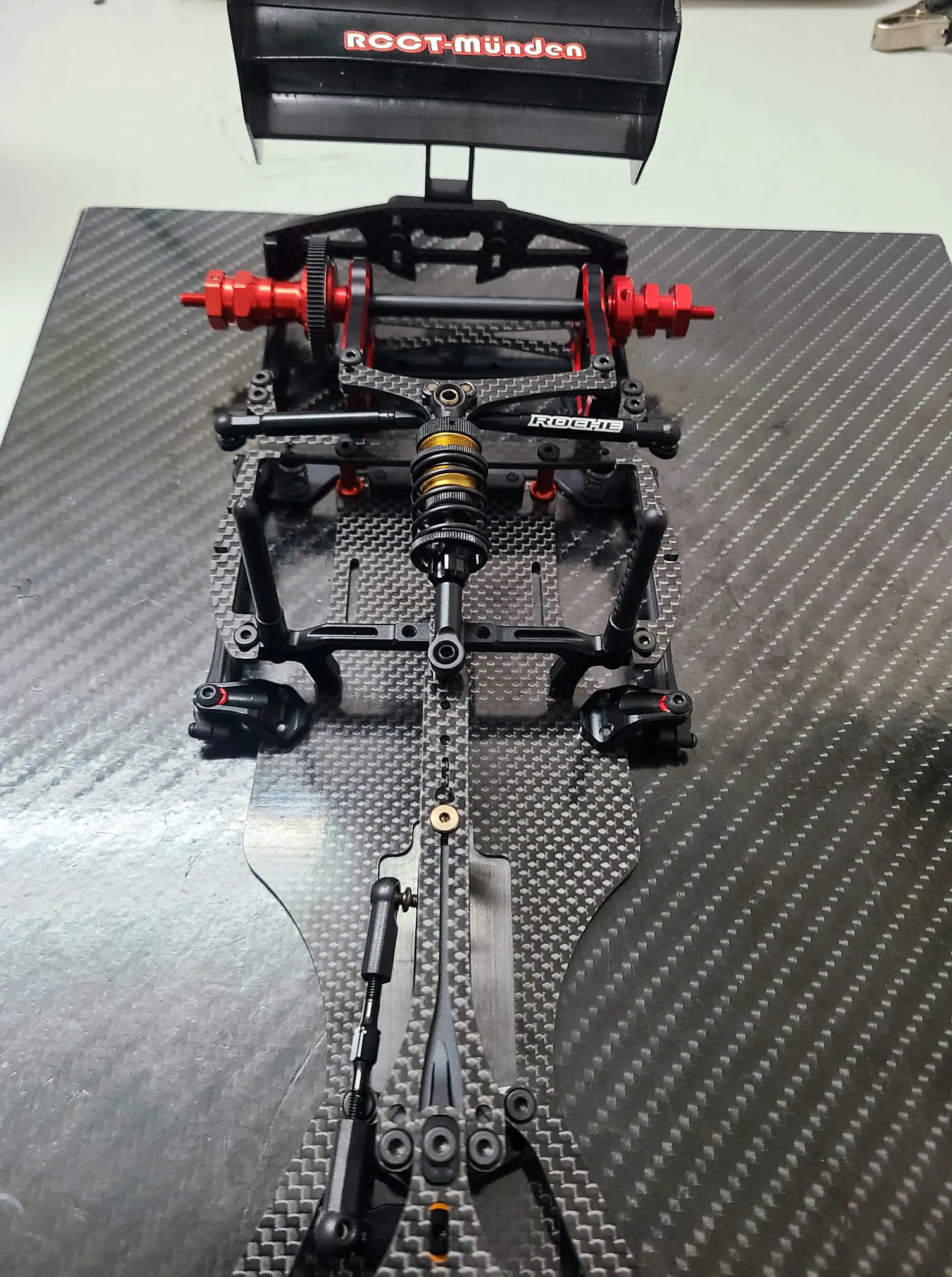
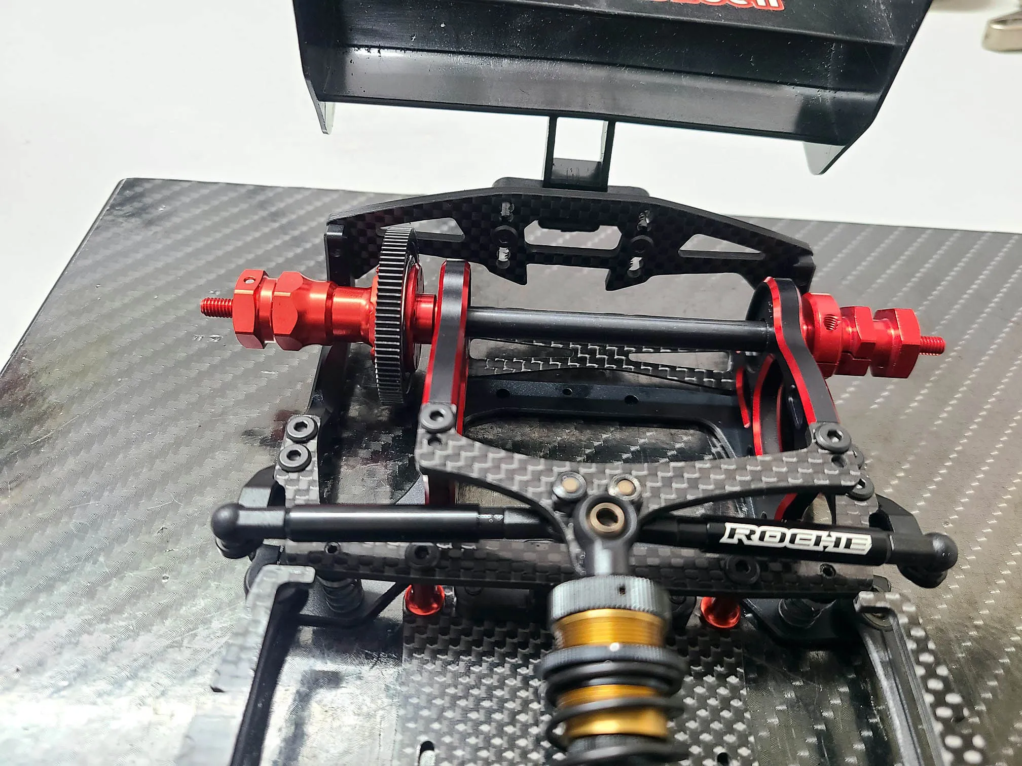
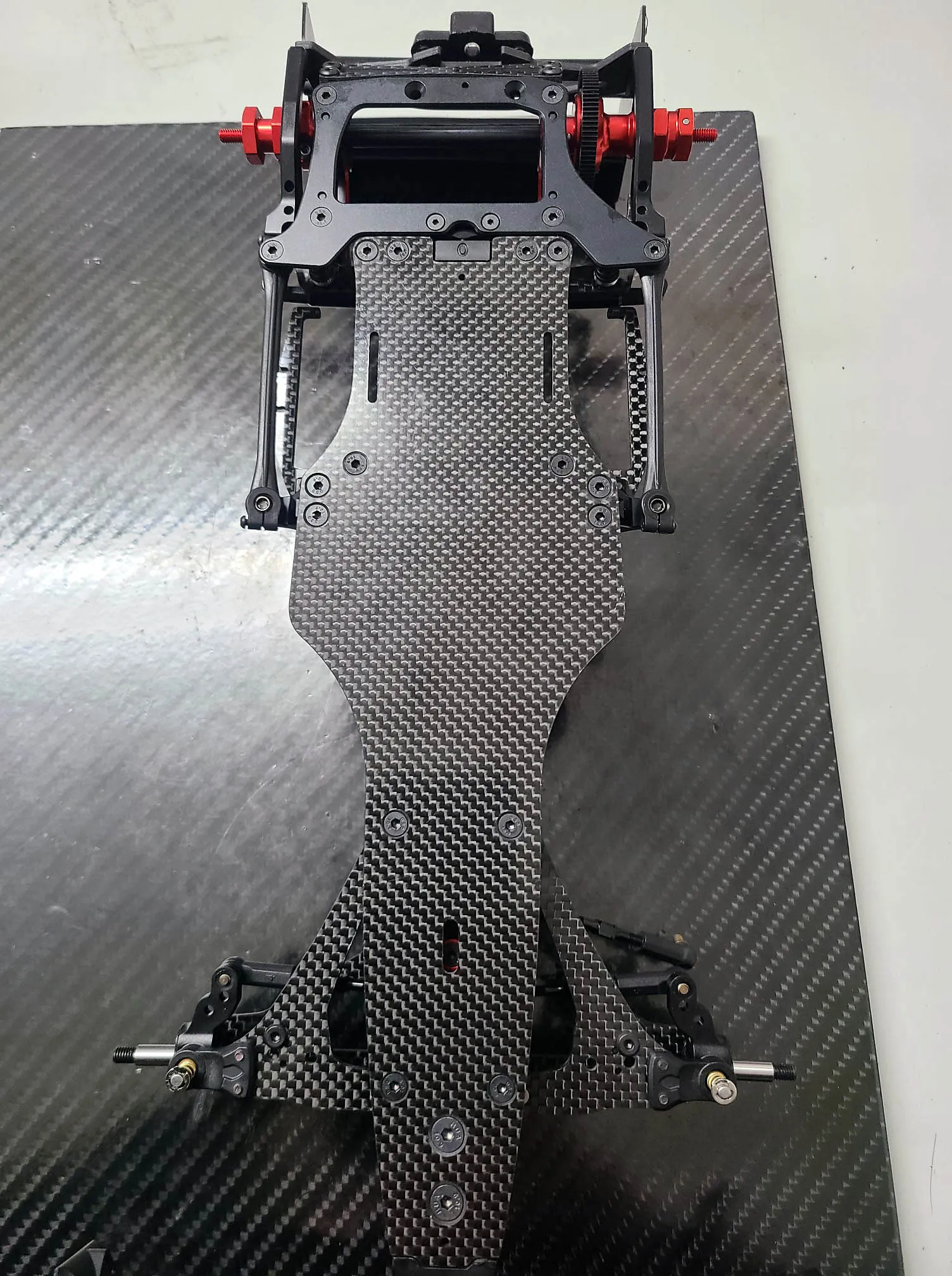
Final pictures starting from here
M. Weffers
Source: M. Weffers